48
[703] - Delay Between Dialing Attempts
For standard (force) dialing, the panel will go off-hook, search for
dialtone for 5 seconds, hang-up for 20 seconds, go off-hook,
search for dialtone for 5 seconds, then dial. If there is no initial
handshake recognized within 40 seconds, the panel will hang up.
This programmable timer adds a delay before the next call is
attempted, and is defaulted to 001 for a total of six seconds.
5.9 Module Programming
The programming sections listed below pertain to additional mod-
ules on the system. For instructions on programming these mod-
ules and a description of each programming section, see the
associated Installation Manuals.
1. PC5400 Programming Section [801]
2. PC59XX Programming Section [802]
• Audio Verification Module provides Talk/Listen-in capability
for audio verification of alarms. Up to 4 microphones and 2
speakers can be connected to the module. The talk/listen-
in options are programmable by the central station opera-
tor using the telephone keys 1-9, [*] and [#]. Please refer to
the PC5900 Installation Manual for more details.
2. Alternate Communicator Programming Section [803]
3. PC5132 Programming Section [804]
4. PC5100 Programming Section [805]
NOTE:
All Talk/Listen and/or video sessions are disconnected
when the panel communicates alarms to the central station.
Telephone 1 & 3 Listen-In Enabled . . . . . . . Section [381], Option 5
Telephone 2 Listen-In Enabled . . . . . . . . . . Section [381], Option 6
5.10 Special Installer Instructions
[900] - Panel Version
This section will display the panel version.
[901] - Installer Walk Test Mode Enable / Disable
The Installer Walk Test can be used to test the alarm state of
each zone of the panel. The walk test cannot be used to test zone
type [24]. Before beginning the walk test, ensure the following
conditions are met:
1. The panel is disarmed
2. The Keypad Blanking option is disabled (section [016]: [3])
3. The Fire Bell is Continuous option is disabled (section [014]: [8])
4. The Transmission Delay is disabled, if Transmission Delay is
not required (section [377])
NOTE:
Fire Troubles are not supported in Walk Test.
To perform a Walk Test, do the following:
1. Enter Installer Programming
2. Enter Section [901]
When any zone is violated the panel will activate the Bell Output
for two seconds, log the event to the Event Buffer. Check the
event buffer to ensure that all zones and FAP keys are functioning
properly.
NOTE:
If there is no zone activity on the system for 15 minutes,
the system will end the walk test and return to the normal state.
To stop the test, you must do the following:
1. Enter Installer Programming
2. Enter Section [901]
Zones do not have to be restored to stop the test. After the test is
complete, check the Event Buffer to ensure that the Audible/Silent
24-hr. PGM alarms have been restored.
NOTE:
The Alarm Memory is cleared upon entering Walk Test
mode. When the Walk Test is complete, the Alarm Memory will
indicate the zones tested. The Alarm Memory will be cleared the
next time the panel is armed.
NOTE: While the walk test is in progress, all three LEDs (Arm,
Ready, Trouble) will flash at a rapid rate. At the start of the Walk
Test, a TS signal will be communicated. When the test is stopped a
TE (test end) is communicated.
[902] - Reset Module Supervision
All modules will automatically enroll within one minute upon
power up (except the PC5132 if there are no serial numbers pro-
grammed). If modules are to be removed, this section should be
entered after the removal of the modules so that it may clear any
supervisory troubles that may be present. When this mode is
entered, the system will re-evaluate the components of the sys-
tem.
NOTE:
It may take up to a minute to enroll or delete a module.
Before entering Section [903] to view the module field, this time
should be taken into account.
If there is a module that is not properly communicating with the
system and this section is entered, the module will be deleted
from the system.
Once executed, all pending Supervisory Trouble Restores will not
be logged or transmitted.
[903] - Module Supervision Field
In this mode, the system will display all of the modules presently
enrolled on the system as indicated below.
[904] - Module Placement Test
Module Selection
Upon entering Section [904], a 2 digit entry will be required to
select the zone number to be tested. Valid entries are 01-32 for
Zones 01-32 respectively. On an LCD Keypad, there are two
ways to make a zone selection: direct entry of “01”-”32”, or by
scrolling across to the description of the module (i.e. “Zone 1”). If
a module is selected that is not enrolled, an error tone will sound.
Placement Indication
After the zone is selected, the alarm contacts must be opened.
This will register a signal strength value that will be indicated and
enunciated on all keypads, as well as on the Bell. The system will
remain in this test mode until [#] is pressed or Installer’s timeout
(20 minutes).
• GOOD signal will be indicated by Light 1 on an LED key-
pad or the word GOOD on an LCD keypad. It will be enun-
ciated on the Keypad by 1 beep and on the Bell by 1
Squawk.
8 FTC Bell ON Bell on FTC when armed If a Failure to Communicate Trouble is generated while the system is
armed, the Bell output will sound for the length of Bell time-out or until the system is disarmed.
OFF FTC Trouble only when armed If a Failure to Communicate Trouble is generated while the panel is
armed, the Bell output will not sound but the keypad buzzer will sound trouble beeps until a key is
pressed.
Option International Code On/Off Description
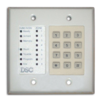
Indicator Module
Lights 1-8 Keypads 1-8
Lights 9-14 Zone Expander Groups 1-6
Light 15 PC5100
Light 16 Zone Expander Group 7
Light 17 Wireless Receiver
Light 18 PC5208
Light 19 PC5204
Light 20 PC5400
Light 21 PC59XX
Light 22 Alternate Communicator
Light 23 For Future Use
Light 24 ESCORT5580(TC)
Light 25 For Future Use
Light 26-29 PC520X 1-4