SLICE User’s Manual support@dtsweb.com
Version 1.0 - May 2010 33 ©DTS, Inc. - All Rights Reserved
Calibration History
! This field is automatically updated whenever a new sensitivity is applied to
the sensor attributes. You cannot enter directly into this field.
Options
! Invert: When checked, the data will be inverted.
! Shunt Check and Bridge Resistance: When Shunt Check is checked, the
sensor will have the bridge resistance measured during diagnostics and
compared to the value entered in Bridge resistance.
! SW Filter: Choose the frequency of a software filter to be applied to the
data when viewing. This only affects the viewed data as all data stored will
be as collected with the hardware anti-alias filter.
! Zero Method (post download software zeroing):
o Use Pre-Cal Zero: The Zero Measured Output (ZMO) of the sensor
during calibration will be used to set the EU zero of the downloaded
data.
o Average Over Time: Used in conjunction with ZeroStart and
ZeroEnd, the average EU value during the Start and End window
will be used to Zero the collected data. The Zero Start/End window
must be set to data that will be collected. If using a negative time,
then the Acquire tab must include this window.
o None: The actual recorded input will not be adjusted or
compensated for zero level. This setting can be used to show the
actual mV offset. An example may be to record a logic level signal
and see the actual on/off state.
o Remove Offset (hardware): When checked, this will remove the
ZMO during diagnostics. This will “electrically” zero the input.
o ZeroStart/End: See Zero Method!Average Over Time.
o Offset Check: Used in conjunction with Limit Low/High during
diagnostics. When checked, the ZMO is measured and compared
the Low/High limits as a pass/fail criteria during diagnostics.
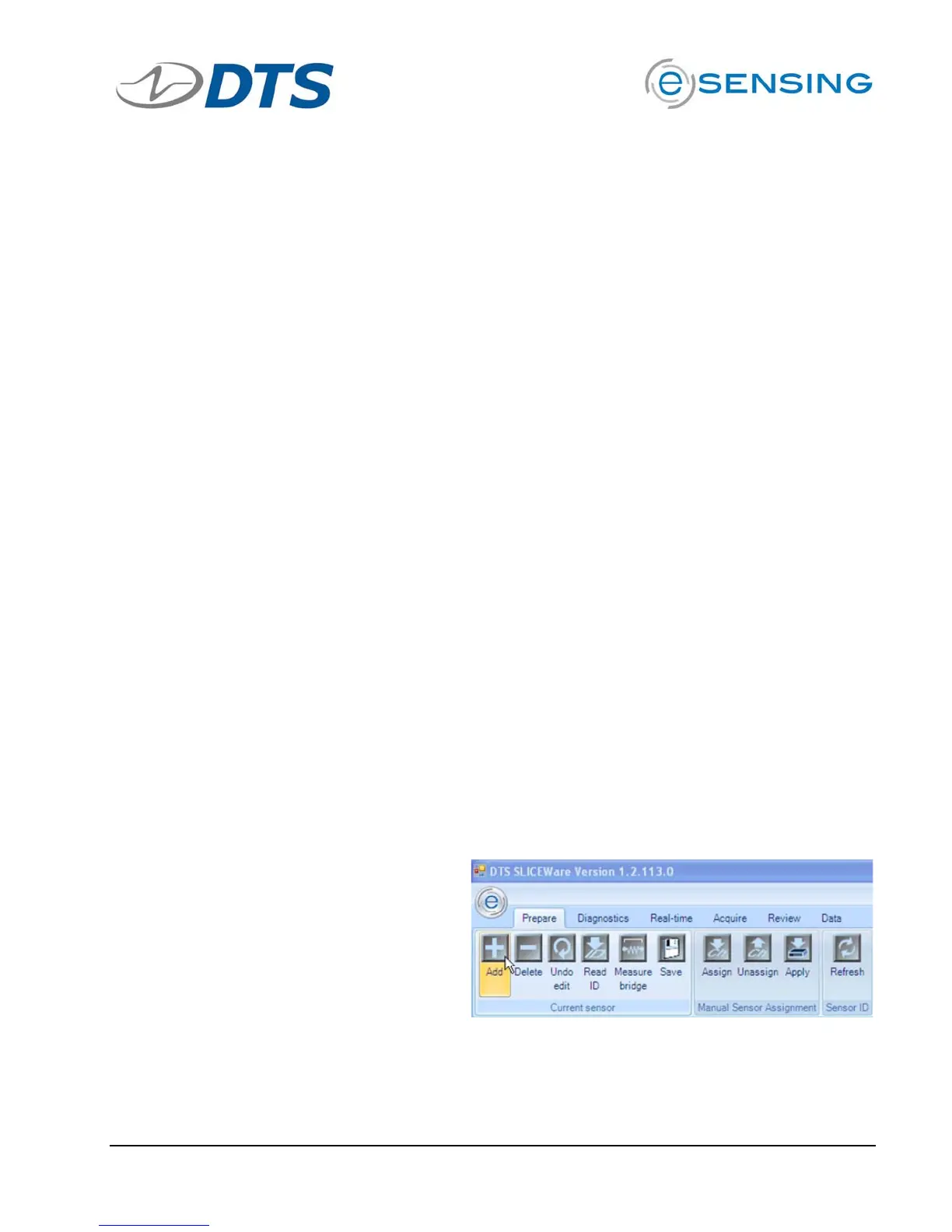
Step-by-Step Procedure to Add a New Sensor
1. On the PREPARE tab,
click the “Add” button in
the “Current Sensor”
button group