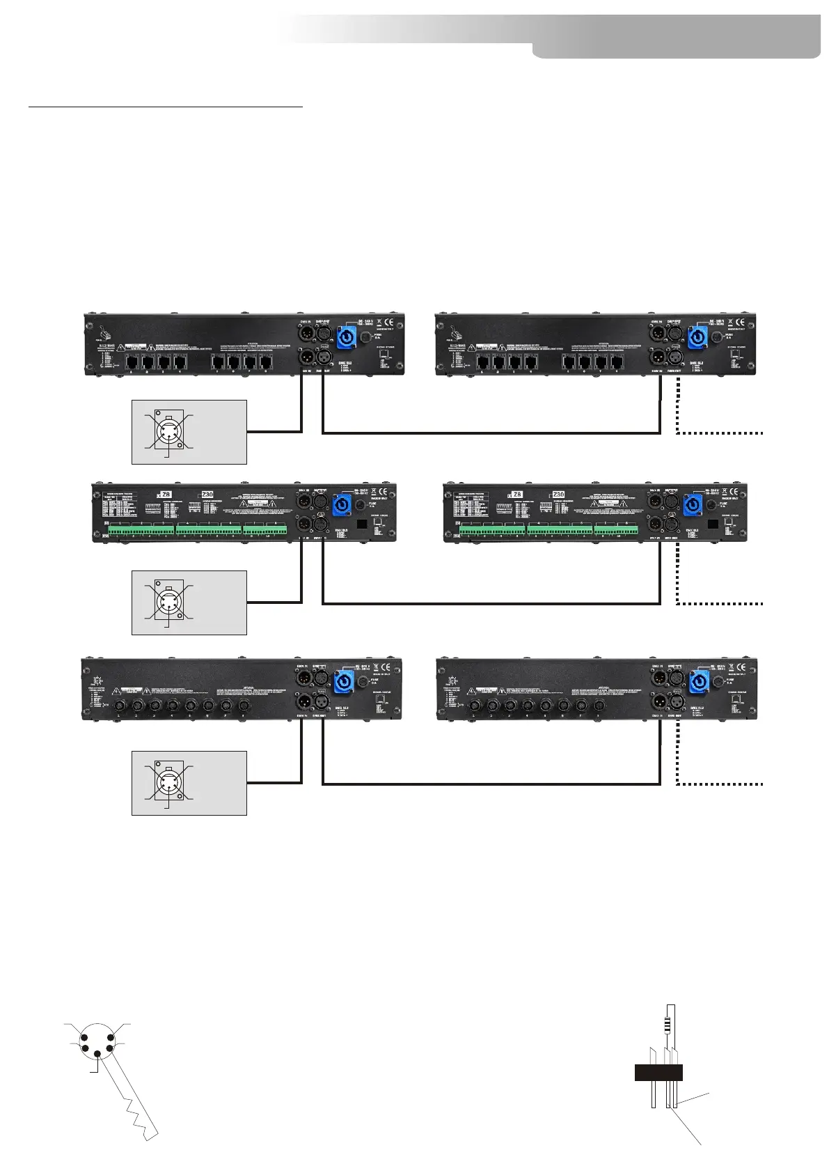
DMX SIGNAL CONNECTION:
The unit operates using a digital DMX 512 signal. Connection between the controller and the unit or
between units must be carried out using a two pair screened ø 0.5 mm cable and a CANNON XLR 5 pins
connector.
P.S:If the display showing the DMX address flashes, then one of the following errors has occurred:
- DMX signal not present
- DMX reception problem
For Installations where long distance DMX cable connections are needed, we suggest to use a DMX
terminator.
The DMX terminator is a male XLR 3-5 pins connector with a 120 ohm resistor Between pin 2 and 3.
The DMX terminator must be plugged into the last unit (DMX out panel connector) of the DMX line.
Ensure that the conductors do not touch each other. Do not connect the cable ground to the XLR
chassis. The plug housing must be isolated. Connect the mixer signal to the DMX IN of the Z8 plug and
connect it to the next unit by connecting the DMX OUT plug on the first Z8 to the DMX IN plug of the
second one.
This way, all the projectors are cascade connected.
1
2
3
5
4
OUT
120 ohm
PIN 3
PIN 2
PLACE A 120 OHM RESISTOR BETWEEN PIN 2
AND 3 OF A MALE XRL CONNECTOR AND PLUG IT
INTO THE DMX OUT PANEL CONNECTOR OF THE
LAST UNIT CONNECTED TO THE DMX LINE
Z8 LED Controller
5
3
4 2
1
1=GND
2=DATA-
3=DATA+
Standard
DMX 512
controller
5
3
4 2
1
1=GND
2=DATA-
3=DATA+
Standard
DMX 512
controller
5
3
4 2
1
1=GND
2=DATA-
3=DATA+
Standard
DMX 512
controller
9