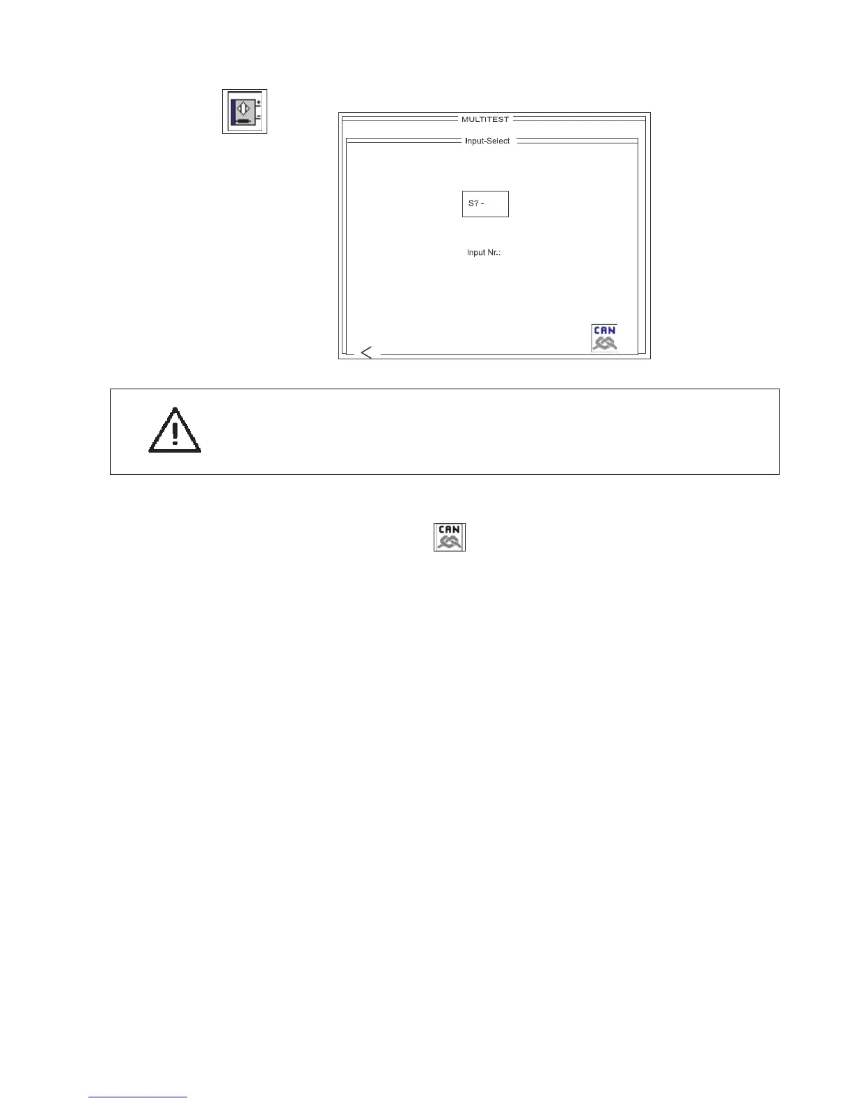
6.4.3 Selecting input elements
This program adjusts the input elements.
CAUTION:
The input elements are factory-set with great care.
Adjustment and correction may only be undertaken by trained service
personnel.
–
Press OK to run the test program.
–
Use the key to select between the basic module and the CAN
node.
–
Enter the code number of the required input element on the
decimal keypad.
The code numbers are the abbreviations used in the circuit
diagram (see table below).
–
The display shows the circuit-diagram designation and the
switching status of the input element selected (e.g. “+S17").
The display changes if the switching status of the input element is
altered.
A switching status of ”+" means:
contact switch = contact open
proximity switch = metal in front of the switch
reflecting light barrier = no reflection
Exception:
S25 and S20
Both input elements respond in the opposite manner,
i.e. “-” means = metal in front of the switch
–
Move the input element until the display shows the required
switching status.
–
To leave the test program press function key F1.
77
 Loading...