. .
Dyadic Systems – Mechatronics Cylinder Manual MF-005500-EN-19/63
3.2.7. Quick Start – Program a Force-Controlled Motion With the Teach Pendant
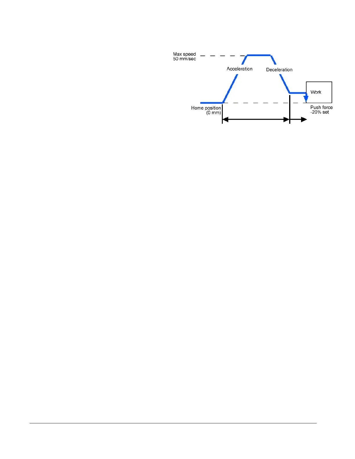
Let’s program the motion as per the figure on
the right, such that the actuator moves
20mm at higher speed, then switches to low
speed to look for a pre-set force.
Please note that the force value is negative
(-) for the extend direction, positive (+)
for the retract direction.
(1) Connect the ADP cable to the Teach Pendant and the serial connector on the servo controller.
(2) Wire the power cable as follows:
RP9100 power cable:
Red (Drive) with +24VDC, Black (Drive) with 0V, Brown (ILK) with +24VDC
RP9120 power cable:
Red (Drive) with +24VDC, Black (Drive) with 0V, Yellow (Control) with +24VDC, White (Control) with
0V, Purpule (ILK) with +24VDC
(3) Please turn the power ON.
(4) 4-5 seconds after the power is turned ON, the Servo ON LED of the Teach Pendant will be ON and the
LCD will be display “Make Homing”. Please press and hold the “homing” button until the display shows
the “Homed” message.
(5) Please turn the JOG handle clockwise and verify that the actuator shaft moves forward.
(6) The following will store push force parameters in position 4.
Please press the “POSITION SELECT” button 4 times such that the position number display indicates
[4]. Now position 4 can be programmed.
Please press the “PUSH POSITIONING” button. Now position 4 is in push force mode.
Check that the “POS. JOG TEACH” LED is lit, and turn the JOG handle to extend the actuator until the
LCD displays position [-20mm]. Press “SAVE” button. This is the position at which the higher speed
part of the move will end and the force controlled part of the move will begin. This is also referred to as
the “Approach Point”.
Please press the “DATA ENTRY MODE” button twice to access the “SPEED DATA INPUT” parameter.
Change the speed to 50mm/sec by turning the JOG handle, then press the SAVE button.
Press the “DATA ENTRY MODE” button 3 times to access the “PUSH FORCE DATA IN” parameter.
Set the push force to -20% by turning the JOG handle, then press the “SAVE“ button.
Now, position 4 has a force-controlled motion programmed as shown in the above figure.
(7) Turn the JOG handle counter clockwise to retract the shaft. Press and hold the “POSITION RUN” button
with number 4 displayed in the seven segment display, and the actuator will operate the push force
motion. If the button is released the motion will stop.