. .
Dyadic Systems – Mechatronics Cylinder Manual MF-005500-EN-23/63
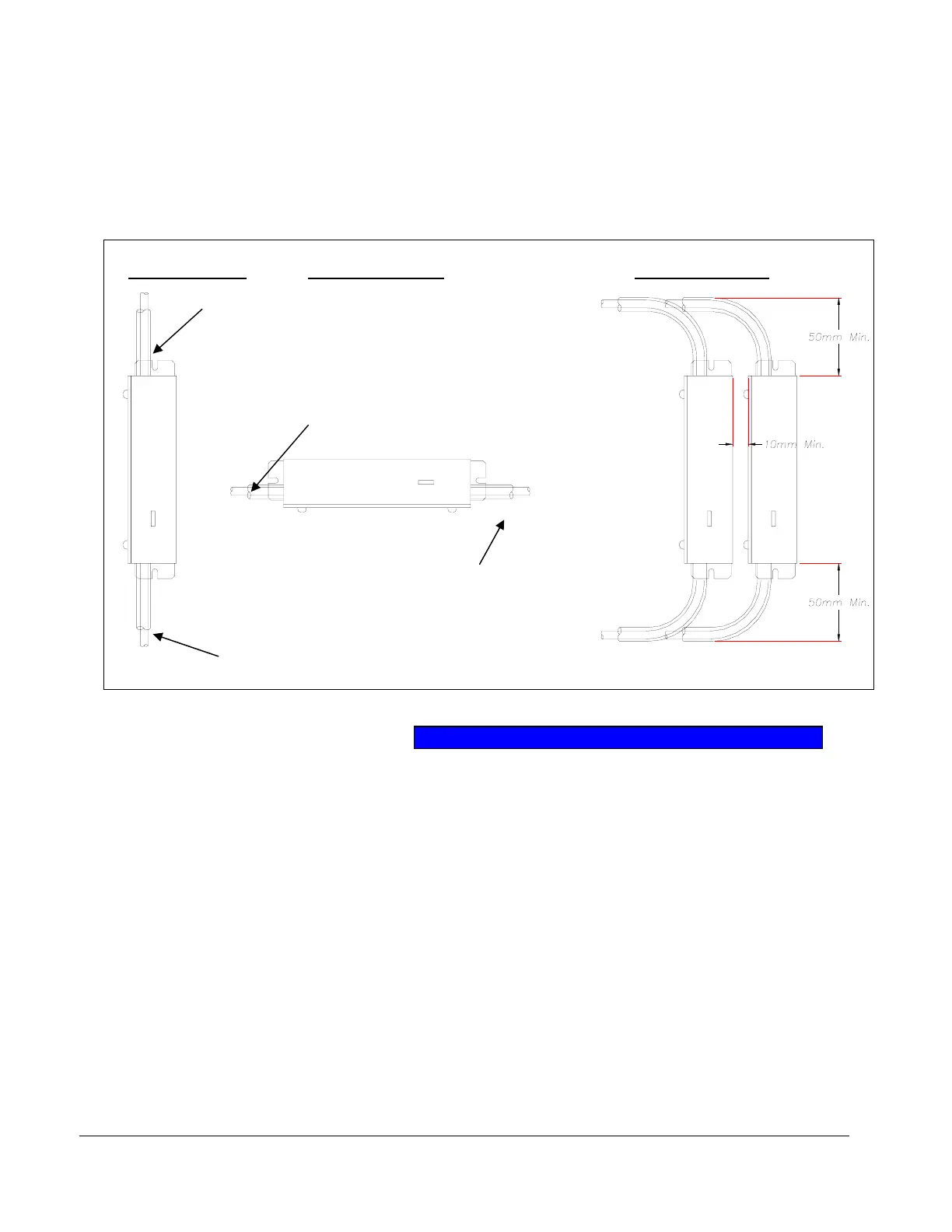
4.1.5. Servo Amplifier Mounting and Environmental Installation Limits
(1) Ambient temperature under 40°C.
(2) Minimal shock and vibration. (should be lower than 0.5G)
(3) Environment free of corrosive gas and dust.
(4) Ambient humidity under 90%RH, non condensing.
(5) Please use 2 ea of M3 screws to mount amplifiers as per the sketch below. Please leave 10mm
distance or greater between amplifiers, and leave 50mm or greater space for cables:
4.2. Wiring
Please wire with reference to section 3.2.3.
4.2.1. Wiring
(1) The following precautions may help to avoid problems with electrical noise:
① The wires from the Controller to the PLC and noise filter should be as short as possible.
② Power to coils of relays and solenoids should be managed by surge hardware.
③ Separate the wiring from other equipment.
(2) When the Mechatronics Cylinder system is being controlled by 24V I/O:
① Design the system to allow shut off of the 24V line to the actuator in case of “SERVO ALARM”.
② The sequences of power up and down should be as follows:
Vertical mounting
Horizontal mounting
Motor, Encoder cables
Power parallel cable &
Serial cable
Top
Lower
Lower
Top
Motor, Encoder cables
Power parallel cable &
Serial cable
Installation distance
PNP T
e