. .
Dyadic Systems – Mechatronics Cylinder Manual MF-005500-EN-26/63
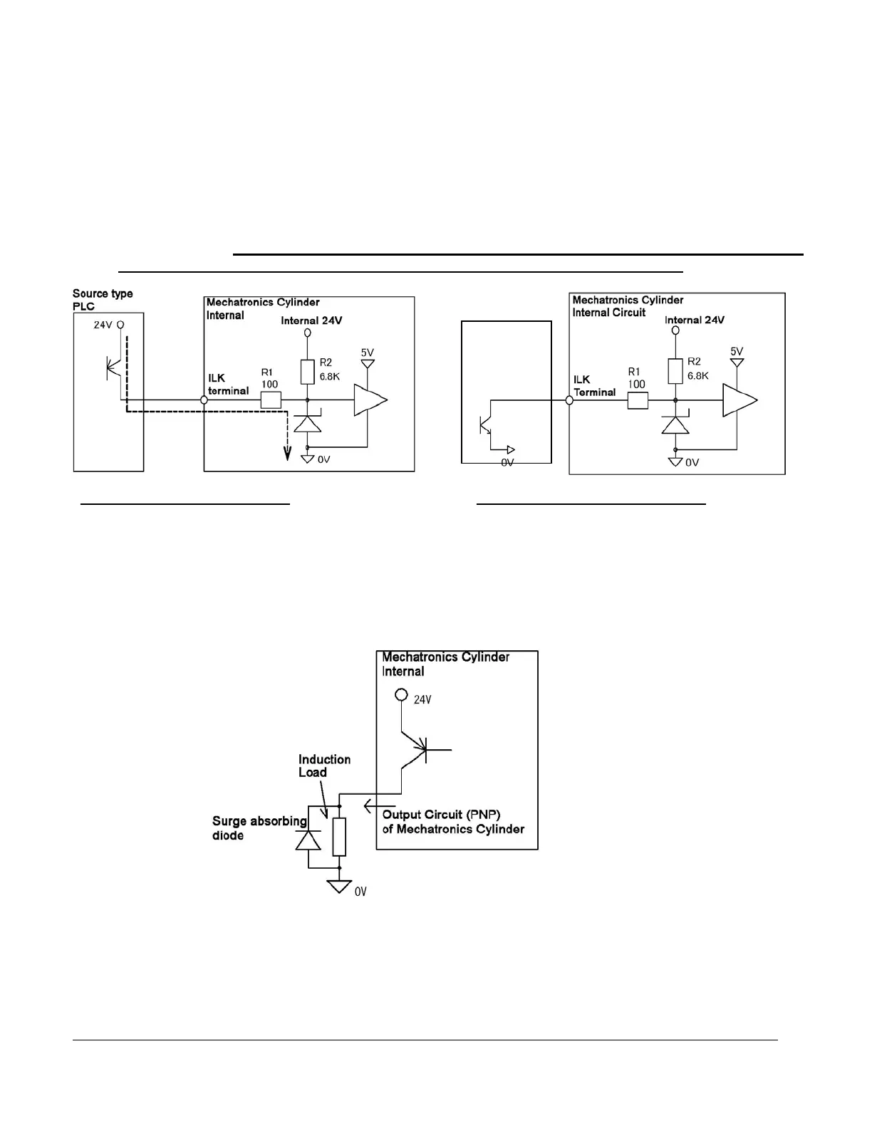
4.3.3. Power input circuit
Ensure all I/O of the Mechatronics Cylinder are connected to either 0VDC or 24VDC±10%.
Connection to any voltage in between these values may result in damage to the input or output.
The input circuits of the Mechatronics Cylinder are designed as non-isolated dedicated source drive
circuits as described below. Therefore it is necessary to connect (ON) with +24V terminal, or open (OFF)
with +24V terminal by using source type output circuit.
As shown below, the input circuit will receive over current and the internal circuit will be damaged
if a PNP input is driven by a sinking output circuit or connected with 0V directly.
4.3.4. When Driving Coils or Other Inductive Loads
When using outputs to drive induction loads:
The output circuits of the Mechatronics Cylinder are open collector outputs as shown below. Therefore
when driving an external load (such as a coil), please use an external surge diode or solid state relay.
Surge voltage can damage the output circuit.
Fig. 2 Good PNP Input Circuit Fig. 3 Bad circuit (PNP) example
X O
Sink type
PLC