. .
Dyadic Systems – Mechatronics Cylinder Manual MF-005500-EN-5/63
1. Summary
The Mechatronics Cylinder consists of a rotary-linear motion transfer mechanism, a stepper motor, an
encoder, and a servo controller. Manufactured by Dyadic Systems, this product can be a replacement for
pneumatic cylinders. Motion is programmed and controlled using Dyadic’s simple interfaces, allowing for a wide
variety of inputs and inter-operability.
1.1. Features
1.1.1 Overcoming weaknesses of Pneumatic Cylinders
(1) Simplifying wiring and related equipment.
(2) Multiple positioning: Easy program for up to 16 motions per axis
(3) Programmable Push Force
MODEL SCLT4-015
SCLT4-030
SC LT6-025 SCLT6-050
-XXX AS -XXX AS -XXX AB -XXX AB
Am plifier B u ilt-in to a c tu a to r External
S troke (m m ) 50 / 100 / 150 / 200 / 300 / 400 / 500 50 / 100 / 150 / 200 / 300 / 400 / 500 / 600 / 700
M ax. Thrust (N ) / (kgf) 150 / 15 300 / 30 250 / 25 500 / 50
M ax. carriable w t at pw r O N (kg) 1.5 2.5 46
P ush m ode m ax. Thrust (N )/(kgf) 105 / 10.5 210 / 21 175 / 17.5 350 / 35
B all screw lead (m m ) 12 6 12 6
M ax. S peed (m m /s) * note 1 700 (680m m /s for 400 (340m m /s for 600 (500m m /s for 350 (600m m : 340m m /s)
500m m stroke) 500m m stroke) for 700m m stroke) (700m m : 250m m /s)
R epeatability (m m ) ± 0.02 ± 0.02 ± 0.2 ± 0.2
B ackla sh (m m ) 0.1 0.1 0.1 0.1
M ax. H or Load w eight (kg) 5 10 16 30
M ax. vertical load (kg) 1.5 2.5 46
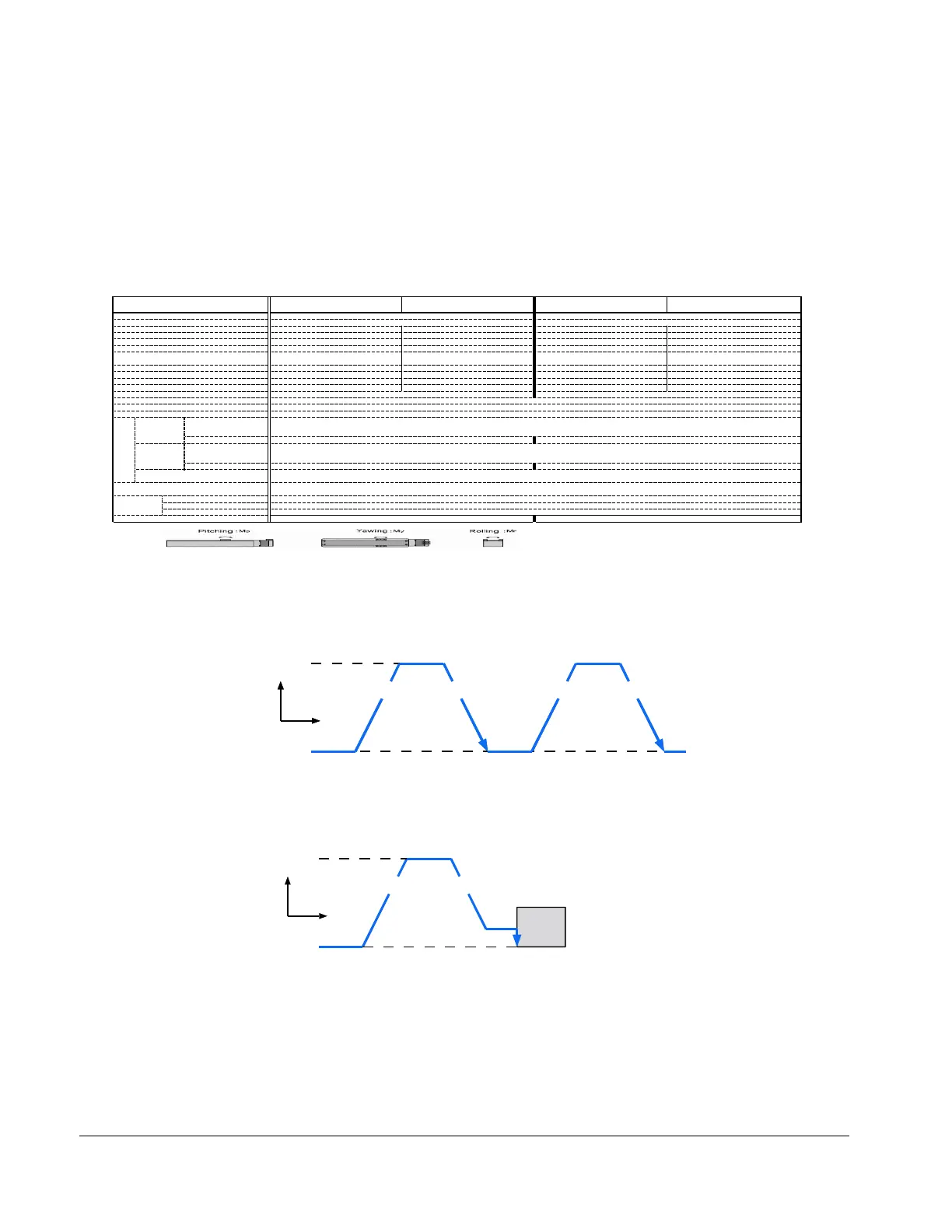
Load m om ent (N m / kgf-cm ) *2 M p=12 / 120, M y=12 / 120, M r= 31 / 310 M p=25.7 / 257, M y=25.7 / 257, M r=58 / 580
P rogram C apacity 16 P ositions
Power Supply D C 24V ± 10% (D rive P ow er m ax. 2.0 A m ps, C ontrol pow er m ax. 0.2A )
Life 3 years after delivery, or 10,000 km operation w hen used w ithin all specs.
P a ra lle l D C 2 4 V ty p e D ig ita l In p u t In te rfa c e
Input N am es P osition select bits (4 bit binary coded decim al: P C 1,P C 2,P C 4,P C 8)
S tart (C S T R ), M ovem ent Interlock (ILK )
Input curren t
M ax. 4m A / port, P N P S tandard M ax. 4m A / port, P N P S tandard
I/O P a ra lle l D C 2 4 V ty p e D ig ita l O u tp u t In te rfa c e
O utput N am es C om pleted P osition N um ber (4bit binary: P M 1,P M 2,P M 4,P M 8) : (S C LT 6 O nly)
H om ed signal (ZFIN ), Z one signal(ZO N E ), A larm (A LM ), P osition com plete (P FIN /IN P )
O utp ut current
M ax. 10m A / port, P N P S tandard M ax. 10m A / port, P N P S tandard
S erial S ignal S erial Interface (C onnector S IO )
+5V , 0V , S + , S -, A S C II P rotocol F reely A vailable
P rotection function O ver speed, M ain pow er over voltage, abnorm al voltage,
O verload, S ensor abnorm al, S ervo abnorm al, E ncoder w ire disconnected
A m bience O perate T em perature 0 ~ 40°C
S torage T em perature -20 ~ 60°C
O pe/S torage H um idity =< 90% R H , non-condensing
W eight (kgs) 1.42/1.53/1.64/1.74/1.96/2.18/2.4 2.7 / 2.9 / 3.1 / 3.3 / 3.7 / 4.1 / 4.5 / 5.0 / 5.4
N o te s : (* 1 ) T y p ic a l d a ta , ( *2 ) T h is is a lo a d th a t th e w t (m k g ) is g e n e ra te d b y th e o v e rh a n g ( L m ) fr o m th e a r rio r s lid e r.
(T he calculation of the load m oe m ent (kgf-cm ) is: m (kg) x L (cm ) < M p, M y, M r)
The actual m om ent will be com binations of those m om ents (M p, P y, M r).
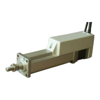
cceleration Deceleration
Programmed
Speed
Stop
condition
Speed
Time
cceleration Deceleration
Work
Programmed
Speed
cceleration Deceleration
Stop
Position
Push
Movement
Speed
Stop
condition
Time