. .
Dyadic Systems – Mechatronics Cylinder Manual MF-005500-EN-37/63
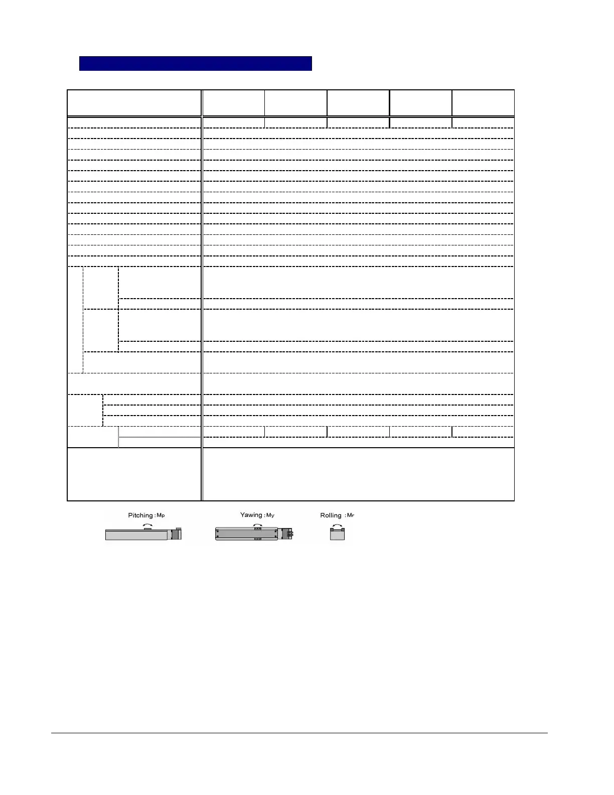
MODEL
SCLG5- SCLG5- SCLG5- SCLG5- SCLG5-
010-050A
010-100A
010-150A
010-200A 010-300A
Stroke (mm) 50 100 150 200 300
Max. Thrust (N) / (kgf) 100 / 10.2
Max. vertical carriable wt at power ON 3 kgs
Push mode max. Thrust (N)/(kgf) 70 / 70.1
Max. Speed (mm/s) * note 1 300
Repeatability (mm) ± 0.1
Backlash (mm) 0.3
Max. Load weight (kgs) 10 (Horizontal)
Max. vertical load (kgs) 2.5
Load moment (N-m) (kgf-cm) Mp=1.5 / 15, My=1.5 / 15, Mr=5 / 51 (* note 2)
Overhang length (mm) * note 3 150 or shorter
Program Capacity 16 Motions
Power Supply DC24V ± 10% (Drive Power max. 3.0 Amps, Control power max. 0.2A)
Life 3 years after the delivery, or 10,000 km operation under the use within the specs.
Parallel DC24V type DI/DO Interface (Connector PIO)
Input Names Position number (4 bit binary: PC1,PC2,PC4,PC8)
Start (CSTR), Axis Movement Interlock (ILK)
Input current
Max. 4mA / port
I/O Parallel DC24V type DI/DO Interface (Connector PIO), Position complete (PFIN/INP)
Output Names Completed Position Number (4bit binary: PM1,PM2,PM4,PM8),
Homed signal(ZFIN), Zone signal(ZONE), Alarm (ALM)
Output current
Max. 10mA / port
Serial Signal Serial Interface (Connector SIO)
+5V, 0V, S+, S-
Protection function Over speed, Main power over voltage, abnormal voltage,
Overload, Sensor abnormal, Servo abnormal, Encoder wire disconnected
Ambience Operate Temperature 0 ~ 40°C
Storage Temperature -20 ~ 60°C
Ope/Storage Humidity =< 90% RH, non-condensing
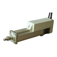
Weight (kgs) Actuator 1.3 1.5 1.7 1.9 2.3
Amplifier 0.5
Functions Positioning with speed, Accele/Decel Servo Gain Adjust
Push Force Mode Stroke Limit end set
Home Direction Set Zone Signal output
Speed Profile
Suitable Auto Max. Accel
Notes: (*1) Typical data, (*2) This is a load that the wt (m kg) is generated by the overhang (L m) from the arrior slider.
(The calculation of the load moement (kgf-cm) is: m (kg) x L (cm) < Mp, My, Mr)
The actual moment will be combinations of those moments (Mp, Py, Mr).
Notes: (*3) This is the acceptable over hand length from the slider carriage.
SCLG5 Mode
Slider Hi
h Ri
idit
T
pe