. .
Dyadic Systems – Mechatronics Cylinder Manual MF-005500-EN-47/63
Number Symbol Functions
1 +24V Main Power DC24V, positive
2 0V Main Power DC24V, common
3 +24V Control Power DC24V, positive
4 0V Control Power DC24V, common
5 PC1 Input of Position registration number: Total of PC1 to PC8
ON means 1, OFF means 0
6 PC2 Input of Position registration number: Total of PC1 to PC8
ON means 2, OFF means 0
7 PC4 Input of Position registration number: Total of PC1 to PC8
ON means 4, OFF means 0
8 PC8 Input of Position registration number: Total of PC1 to PC8
ON means 8, OFF means 0
9 CSTR Strobe input for Input of Position registration number
1. At the edge of OFF=>ON, the controller reads the sum of PC1~8, then it will
move the cylinder to the target position.
2. At the edge of OFF=>ON of when Home is unknown, the cylinder will move
to home, then move to the target position automatically.
10 NC No connection
11 NC No connection
12 ILK Axis movement Interlock input
E-Stop Input Mode
1. If the ILK signal is interrupted (switched to OFF) during the rotation, it will
stop the cylinder with full power and register the position where the cylinder
stopped as its temporary target position.
2. When the ILK
signal is resumed, the registered temporary position will be
deleted and the axis will immediately resume the previously commanded
motion to the original target position. (“Cancel” function is also available)
13 NC No connection
14 NC No connection
Reference : Position number combination Table (for all models)
Position Number
Resister
0 1 2 3 4 5 6 7 8 9 A B C D E F
PC1 0 1 0 1 0 1 0 1 0 1 0 1 0 1 0 1
PC2 0 0 1 1 0 0 1 1 0 0 1 1 0 0 1 1
PC4 0 0 0 0 1 1 1 1 0 0 0 0 1 1 1 1
PC8 0 0 0 0 0 0 0 0 1 1 1 1 1 1 1 1
CSTR (At Starting up, Data of PC1 to PC8 will be read)
SCN
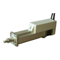
Models
SCL
Models.
SCLL Mode
Externa
amplifier t
pe