Maintenance Manual (960-945) 4-27
Replacement Procedures
4.22.2 Installing the 3G antennas
To install the 3G antennas, follow the steps below and refer to Figure 4-29
to Figure 4-30.
1. Stick new 3G antennas (AUX/Main) in place.
2. Arrange the 3G antenna cables and SAR harness in place on the
Cover Assembly, and fix them with the stick stapes.
3. Connect the SAR harness to the connector CN2650 on the USB board
(FMERLT*).
4.23 System board
4.23.1 Removing the System board
To remove the system board, follow the steps below and refer to Figure 4-
31 to Figure 4-33.
1. Disconnect the Keyboard FPC from the connector CN3240 and
Keyboard Backlight harness from the connector CN3270 on the
System Board (FMERSY*).
1. If replacing with a new system board, update the DMI information as
described in Chapter 3, Tests and Diagnostics. Also update with the
latest BIOS and EC/KBC as described in Appendix G, BIOS Rewrite
Procedures, and Appendix H, EC/KBC Rewrite Procedures.
2. When replacing the system board with a new one, the ProductKey
(MBR-DPK) must be written on the system board.
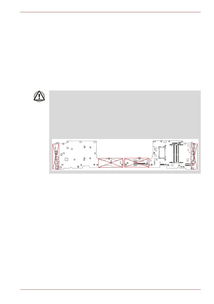
3. When removing/installing the system board, do not handle with the
handling prohibition area.
 Loading...