EasyManuals Logo

dynabook TECRA A40-J Series Maintenance Manual

dynabook TECRA A40-J Series
168 pages
To Next Page IconTo Next Page
To Previous Page IconTo Previous Page
Page #92 background imageLoading...
Page #92 background image
Maintenance Manual (960-945) 4-16
Replacement Procedures
4.15 Smart Card slot
4.15.1 Removing the Smart Card slot
To remove the Smart Card slot unit, follow the steps below and refer to
Figure 4-13 to Figure 4-15.
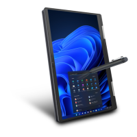
1. Disconnect the FPC/FFC from the connector CN9600 on the SYSTEM
board and CN9640 on the USB board.
Figure 4-13 Removing the Smart Card slot (1)
2. Peel off the INSU SC from the Smart Card slot.
3. Disconnect the Smart Card FFC from the connector CN2170 on the
system board.
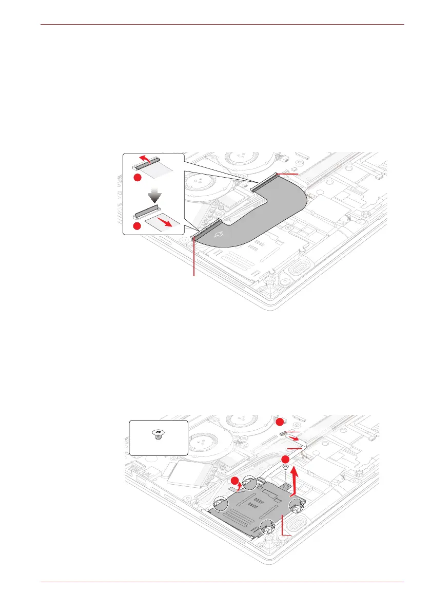
4. Remove the following screw and peel off the AL TAPE. Then slide and
lift the Smart Card slot unit shown in the following figure to remove the
Smart Card slot.
Figure 4-14 Removing the Smart Card slot (2)
SU
B
SUB
1
2
CN9600
CN9640
2
3
1
C
C
FF
C
Card s
CN2170
Smart Card Slot FFC
S2x2BT
Smart Card slotSmart Card slotSmart Card Slot

Table of Contents

Other manuals for dynabook TECRA A40-J Series

Questions and Answers:

Question and Answer IconNeed help?

Do you have a question about the dynabook TECRA A40-J Series and is the answer not in the manual?

dynabook TECRA A40-J Series Specifications

General IconGeneral
Operating SystemWindows 10 Pro
Battery LifeUp to 10 hours
GraphicsIntel Iris Xe Graphics
BluetoothBluetooth 5.1
ProcessorIntel Core i5-1135G7 or i7-1165G7
Display14.0" FHD (1920 x 1080) Anti-Glare
RAM8GB/16GB DDR4
Storage256GB/512GB SSD
WirelessIntel Wi-Fi 6 AX201
Ports2 x USB 3.2 Type-A, 1 x USB 3.2 Type-C, HDMI, Ethernet, MicroSD card slot
SecurityFingerprint Reader, TPM 2.0
WebcamHD Webcam

Related product manuals