EasyManuals Logo

dynabook TECRA A40-J Series Maintenance Manual

dynabook TECRA A40-J Series
168 pages
To Next Page IconTo Next Page
To Previous Page IconTo Previous Page
Page #107 background imageLoading...
Page #107 background image
Maintenance Manual (960-945) 4-31
Replacement Procedures
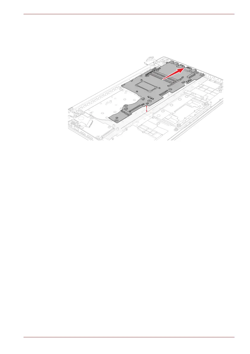
To install the system board, follow the steps below and refer to Figure 4-31
to Figure 4-34.
1. Set the system board in place.
Figure 4-34 Installing the system board
2. Secure the system board with the screws.
3. Connect the LCD/Webcam harness to the connector CN5390 and DC
IN harness to the connector CN8001 on the System Board (FMERSY*)
and arrange the harness to the guide on the Cover Assembly.
4. Connect the Keyboard FPC to the connector CN3240 and Keyboard
Backlight harness to the connector CN3270 on the System Board
(FMERSY*).
4.24 DC IN jack
4.24.1 Removing the DC IN jack
To remove the DC IN jack, follow the steps below and refer to Figure 4-35.
1. Release two screws securing the right display hinge and rotate the
display hinge to upright position.
2. Release the DC IN jack harness from the guide, and remove the DC IN
jack from the slot on the Cover Assembly.

Table of Contents

Other manuals for dynabook TECRA A40-J Series

Questions and Answers:

Question and Answer IconNeed help?

Do you have a question about the dynabook TECRA A40-J Series and is the answer not in the manual?

dynabook TECRA A40-J Series Specifications

General IconGeneral
Operating SystemWindows 10 Pro
Battery LifeUp to 10 hours
GraphicsIntel Iris Xe Graphics
BluetoothBluetooth 5.1
ProcessorIntel Core i5-1135G7 or i7-1165G7
Display14.0" FHD (1920 x 1080) Anti-Glare
RAM8GB/16GB DDR4
Storage256GB/512GB SSD
WirelessIntel Wi-Fi 6 AX201
Ports2 x USB 3.2 Type-A, 1 x USB 3.2 Type-C, HDMI, Ethernet, MicroSD card slot
SecurityFingerprint Reader, TPM 2.0
WebcamHD Webcam

Related product manuals