List of Figures
Figure 1: Eddy Current Drive & Control Block Diagram ............................................................................. 5
Figure 2: EC 2000 Keypad Display ............................................................................................................... 6
Figure 3: Standard Panel Dimensions ....................................................................................................... 12
Figure 4: Keypad Cutout Template ........................................................................................................... 13
Figure 5: Keypad Dimensions .................................................................................................................... 14
Figure 6: Standard NEMA Rated Enclosure Dimensions .......................................................................... 15
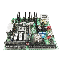
Figure 7: “TB1” Terminal Block .................................................................................................................. 16
Figure 8: Start/Stop/Jog & E-STOP Wiring ................................................................................................ 17
Figure 9: Setpoint Reference & Manual/Auto Mode Wiring ................................................................... 17
Figure 10: Programmable Analog Outputs Wiring ................................................................................... 18
Figure 11: Current Transformer Wiring for Torque Limiting .................................................................... 18
Figure 12: Preset Speeds and PLC Run Wiring .......................................................................................... 19
Figure 13: Speed Pickup Wiring ................................................................................................................ 19
Figure 14: Relay 1-4 Connection Diagram ................................................................................................ 20
List of Tables
Table 1: EC 2000 Jumper Settings ............................................................................................................. 20
Table 2: Follower Setpoint Jumper Settings ............................................................................................. 21
Table 3: Torque Limiting SW1 Settings ..................................................................................................... 21
Table 4: Keypad Button Descriptions ....................................................................................................... 22
Table 5: Mechanical Unit Tach Pulses/REV Setting .................................................................................. 23
Table 6: Ethernet IP/Serial Data Acquisition ............................................................................................ 43