2388-MANUL-V10.00.00-UTP2 Operating Manual
Page 15 of 74
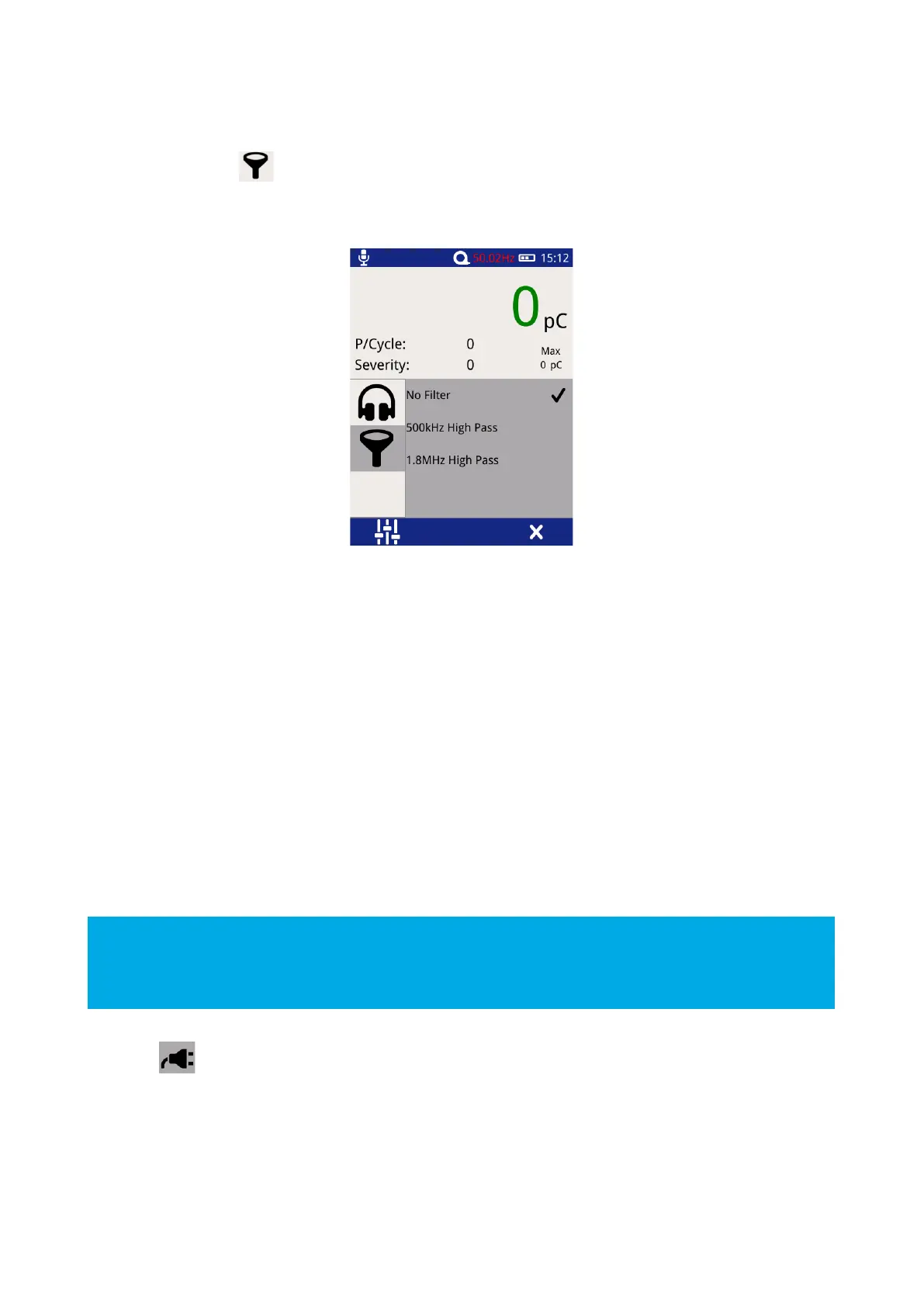
3.11.2 Filters
Select the filter icon to change the filter properties; this option is only enabled when in Cable PD
Measurement Mode and enables noise to be filtered from the cable PD measurement.
Select the desired filter properties, a tick should appear when a selection has been made (shown above).
No Filter – This option passes all frequency types.
500 kHz High Pass – This option activates a high pass filter that passes all frequencies from 500kHz and above.
1.8 MHz High Pass – This option activates a high pass filter that passes all frequencies from 1.8 MHz and
above.
3.11.3 Phase Reference
A properly ‘phase referenced’ Phase Plot will assist in the classification of potential partial discharge activity
that has been recorded. It will provide a much clearer Phase Plot that can be analysed later and compared to
other readings/phase plot patterns.
The most important time to achieve a phase reference is when a number of events (or discharges) are being
captured and they are clustering on the screen of the UTP2.
For more information on phase reference, contact product-support@eatechnology.com
Select the icon on the context menu to access the phase reference settings page. This allows the source
of the phase reference for the UTP2 to be selected from the following options:
Photo – This option selects the Photo-sensor located on the front upper section of the UTP2 (see Figure 1) as
the source of the Phase reference. The Photo-sensor requires line of sight to a mains frequency light source
such as a fluorescent fitting.