2388-MANUL-V10.00.00-UTP2 Operating Manual
Page 16 of 74
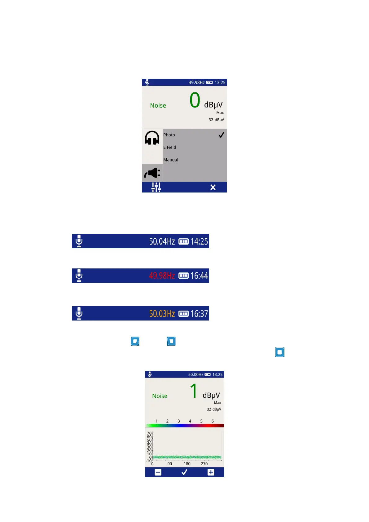
E field – This option selects the built-in E-field sensor as the source of Phase reference. The sensor detects the
phase reference from the stray electric field within the substation.
Manual – Allows the user to manually adjust the phase reference.
The current status of the phase reference is indicated by the colour of the phase readout.
A white phase display indicates a
phase lock has been achieved.
A red phase display indicates that a
phase lock has not been achieved. A
continous red phase display would
neccesitate the change of mode.
An amber phase display indicates that
the frequency has been set manually.
When in Manual Mode the Right and Left buttons can be used to increase or decrease the phase
reference respectively. Once the desired value has been reached, press the middle button to store as shown
below.