10
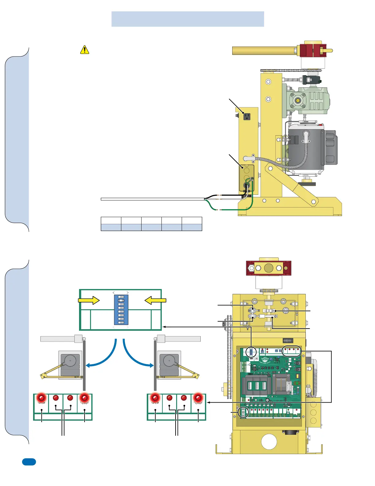
Input Power ConnectionLimit Switches
MASTER
OPEN RIGHT
BRAKE ON
REVERSE LOOP NC
ONE PASS
STOP-REVERSE
ALM-RST
CLOSE TIMER
OFF—ON
SLAVE
OPEN LEFT
BRAKE OFF
REVERSE LOOP NO
OPN DLY S
OPN DLY M
OPN DLY S
OPN DLY M
MASTER
SLAVE
1
ON
2 3 4 5 6 7 8
SELECT
Diamond Board 120 VAC Input Power Connection
Setting the Limit Switches
WARNING: Eagle Access Control Systems, Inc. is not responsible for
researching and complying with local building codes. Be sure to check
all local building codes before installation.
Be sure that the circuit breaker for the input power is turned OFF
before connecting the input power to the operator.
All operators MUST be properly grounded. Installing surge protection
is recommended.
The limit switches MUST be set so the gate stops at the correct open and close positions.
the control board MUST have power for the limit LEDs when setting the limit switches
Adjust the close limit switch FIRST when the gate is in the closed position.
Open and Close
Limit LEDs will light
up on control board
for top or bottom
limit switches as
indicated.
Indicates the
direction the
gate is cycling.
IMPORTANT: DO NOT
cycle the operator before
setting the limit switches.
Damage or injury could
occur if limit switches are
NOT set. (See below)
Junction Box
Top Limit Switch
Top Limit
Switch
Bottom Limit
Switch
Top Limit
Switch Activator
Bottom Limit
Switch Activator
OPEN LEFT OPEN RIGHT
Bottom Limit Switch
3-button
station
cycles
operator.
120 VAC power
outlet provided.
Wire Color Description
Black - 120 VAC input power
White - Neutral input
Green - Ground input
(from an approved grounding method)
250 ft
14 AWG
400 ft
12 AWG
650 ft
10 AWG
1000 ft
8 AWG
2000 ft
4 AWG
CAUTION
MASTER
OPEN RIGHT
BRAKE ON
REVERSE LOOP NC
ONE PASS
STOP-REVERSE
ALM-RST
CLOSE TIMER
OFF—ON
SLAVE
OPEN LEFT
BRAKE OFF
REVERSE LOOP NO
OPN DLY S
OPN DLY M
OPN DLY S
OPN DLY M
ACTIVE
OVERLOAD
OPENING
LIGHT HEAVY
ERD STATUS
GATE STATUS
Eagle Diamond Control Board
Rev A4
TIMER
MIN
MASTER
SLAVE
MAX
1
ON
2 3 4 5 6 7 8
M/S PHASE
01
CLOSING
SELECT
OPEN
LIMIT
OPENING CLOSING CLOSE
LIMIT
CLOSE
STOP
OPEN
SLAVE MASTER
+ – + –
#14#13
+ MAGLOCK
- 24 VDC
#10
+ ALARM
- 12 VDC
#11
MAGLOCK
RELAY
#9
POWER
24 VAC
#12
REVERSE
LOOP
#2
PHANTOM
LOOP
#3
EXIT
OPEN
#4
KEY
KEYPAD
#6
EDGE
SENSOR
#8
STOP
#5
CLOSE
#7
GND
GND
RCVR
24VAC
#1
LOOP WIRE INPUT
EXIT
OPEN
SHADOW
LOOP
REVERSE
LOOP
COMM PORTOUTPUTSGLOBAL INPUTS
RECEIVER
REVERSE LOOP SHADOW LOOP EXIT LOOP
REVERSE SHADOW EXIT
RESET
OFF ON
Power Switch
To Set the Limit
Switches:
Loosen set screw and
rotate top and bottom
limit switch activators
accordingly.
Set Screw
Feature Selector #2
GATE STATUS
OPEN
LIMIT
OPENING CLOSING CLOSE
LIMIT
Indicates the
direction the
gate is cycling.
Bottom Limit
Switch
Top Limit
Switch
GATE STATUS
OPEN
LIMIT
OPENING CLOSING CLOSE
LIMIT
MASTER/SLAVE INPUT POWER NOTE:
Industrial setting using 3-phase must be
on the same phase.
Single Operator 120 VAC Input Wire
Guidelines
Green
120 VAC Input Power Wire
Black wire to Black wire.
White wire to White wire.
Green wire to Green wire.
Black
White
120 VAC
Diamond Board ONLY