17
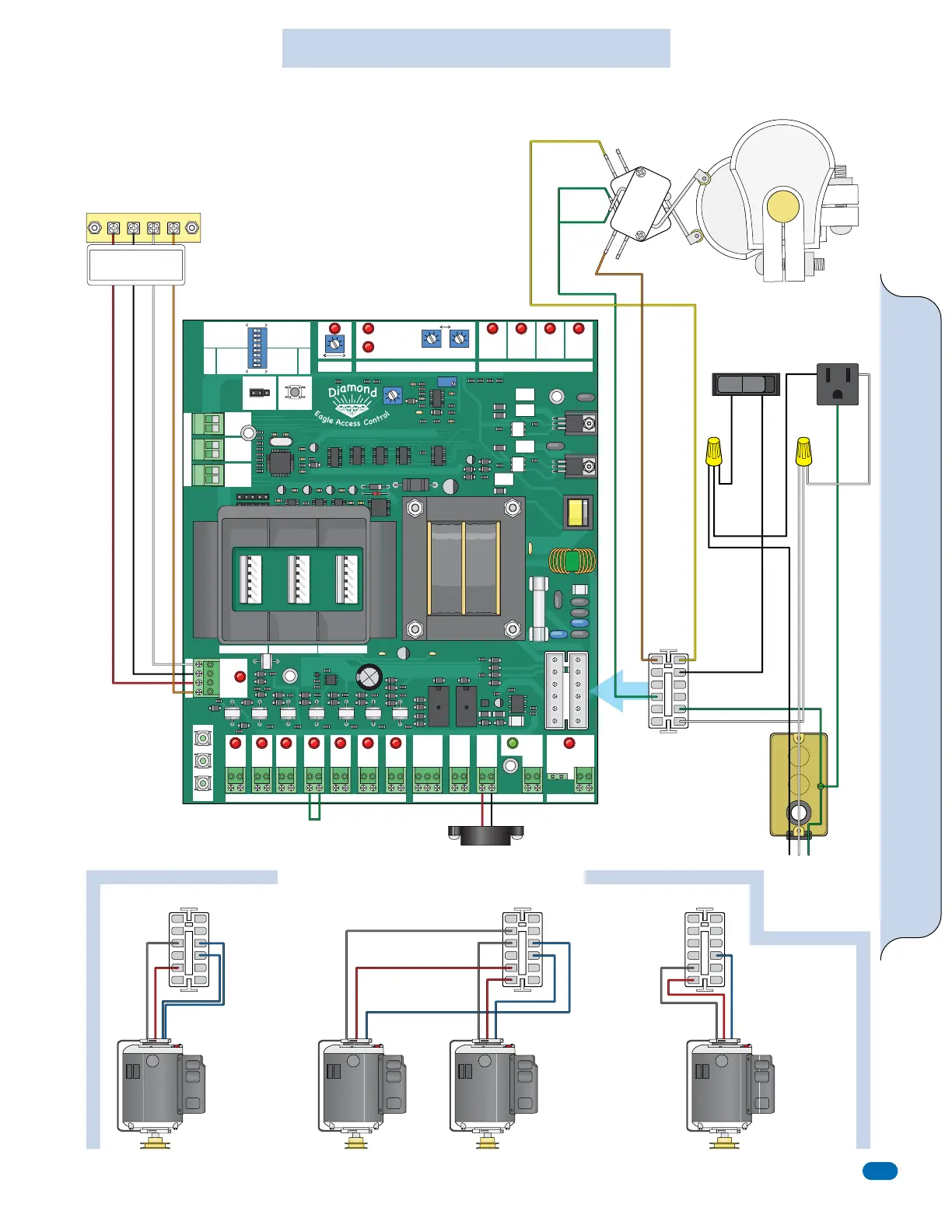
Diamond Board Wiring Diagram
MASTER
OPEN RIGHT
BRAKE ON
REVERSE LOOP NC
ONE PASS
STOP-REVERSE
ALM-RST
CLOSE TIMER
OFF—ON
SLAVE
OPEN LEFT
BRAKE OFF
REVERSE LOOP NO
OPN DLY S
OPN DLY M
OPN DLY S
OPN DLY M
ACTIVE
OVERLOAD
OPENING
LIGHT HEAVY
ERD STATUS
GATE STATUS
Eagle Diamond Control Board
Rev A4
TIMER
MIN
MASTER
SLAVE
MAX
1
ON
2 3 4 5 6 7 8
M/S PHASE
01
CLOSING
SELECT
OPEN
LIMIT
OPENING CLOSING CLOSE
LIMIT
CLOSE
STOP
OPEN
SLAVE MASTER
+ – + –
#14#13
+ MAGLOCK
- 24 VDC
#10
+ ALARM
- 12 VDC
#11
MAGLOCK
RELAY
#9
POWER
24 VAC
#12
REVERSE
LOOP
#2
PHANTOM
LOOP
#3
EXIT
OPEN
#4
KEY
KEYPAD
#6
EDGE
SENSOR
#8
STOP
#5
CLOSE
#7
GND
GND
RCVR
24VAC
#1
LOOP WIRE INPUT
EXIT
OPEN
SHADOW
LOOP
REVERSE
LOOP
COMM PORTOUTPUTSGLOBAL INPUTS
RECEIVER
REVERSE LOOP SHADOW LOOP EXIT LOOP
REVERSE SHADOW EXIT
RESET
Eagle-100 / Eagle-200 Models Wiring Diagram
Radio
ReceiverTerminal
Dual Motors
Limit Switches
Power
Switch
115 VAC
Outlet
115 VAC
Input
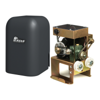
Eagle-100
Eagle-200Eagle-200-DMEagle-200-1HP
Orange N.O. (Top Switch)
Ground
Black
White
Green
Red
White
Black
Red
Orange
Black
Gray
Gray
Gray
2 1/2” Pulley2 1/2” Pulley 2” Pulley2” Pulley
Red
Red
Red
Blue
Green
Green Com
Black
Hot
Black
12-Pin
Plug
12-Pin Plug12-Pin Plug12-Pin Plug
Green
Green
Gray
Red
Blue
Blue
Blue
Blue
White
Neutral
Yellow N.O. (Bottom Switch)
OFF
ON
1/2 HP
Motor
1 HP
Motor
1/2 HP
Motor
1/2 HP
Motor
3
Wire
24V
RADIO POWER
RELAY
RELAY RET
3214
(24V)
COMMON GROUND
4
Wire
24V
RADIO POWER
RELAY
(24V)
RET
2
12
11
10
9
8
7
6
5
4
3
2
1
3
4
17
8
1
2
3
4
7
8
9
11
12
1
4
6
2
7
8
11
12
11
12
9
10
5
6
Junction Box
Diamond Board
Alarm
Motor Wire Configurations
Adding YOUR selected
operator motor wire
configuration from the
three illustrations below to
this 12-pin plug will
complete YOUR selected
operator wiring diagram.
Diamond Board ONLY