19
MH4
DIAMOND
DC
M/S PHASE
01
MASTER
OPEN RIGHT
BRAKE ON
REVERSE LOOP NC
ONE PASS ON
STOP-REVERSE ON
ALARM-RESET ON
CLOSE TIMER ON
OFF—ON
1
ON
2 3 4 5 6 7 8
SELECT
ACTIVE
OVERLOAD
OPENING
LIGHT HEAVY
ERD STATUS
GATE STATUSTIMER
MIN
MAX
CLOSING
OPEN
LIMIT
OPENING CLOSING CLOSE
LIMIT
CLOSE
STOP
OPEN
SLAVE MASTER
#14#13
+ MAGLOCK
- (24 VDC)
#10
+ ALARM
- (12 VDC)
#11
MAG LOCK
N / C
N / O
COM
#9
POWER
24 VDC
#12
REVERSE
LOOP
#2
SHADOW
LOOP
#3
EXIT
OPEN
#4
KEY
KEYPAD
#6
EDGE
SENSOR
#8
STOP
#5
CLOSE
#7
LOOP WIRE INPUT
EXIT
OPEN
SHADOW
LOOP
REVERSE
LOOP
COMM PORT
OUTPUTSGLOBAL INPUTS
RECEIVER
RELAY
-24VDC
RELAY
24VDC
#1
REVERSE LOOP SHADOW LOOP EXIT LOOP
REVERSE SHADOW EXIT
RESET
+ –
+ –
+ –+ –
GND
CLK
GND
CLK
AC POWER
24VAC
SOLAR
POWER
LOW
BATTERY
CHARGER
ON
FUSE MAX 20A
FUSE MAX 35A
20
FUSE MAX 20A
MOTOR
+
–
BATTERY
+
24VAC
HNG
–
LEFT RIGHT GND
GND LEFT RIGHT
20
SOLAR
+
–
–
1
2
3
+
OFF
OFF
OFF
1
ON
2 3 4
P/O ADJUST
1
ON
2 3 4
AUTO OPEN OFF
POWER FAIL OPEN
OPEN DELAY MASTER OFF
OPEN DELAY SLAVE OFF
AUTO OPEN ON
POWER FAIL CLOSE
OPEN DELAY MASTER ON
OPEN DELAY SLAVE ON
OFF—ON
PWR FAIL OPERATION
20 Amp
MH2
MH1
MH3
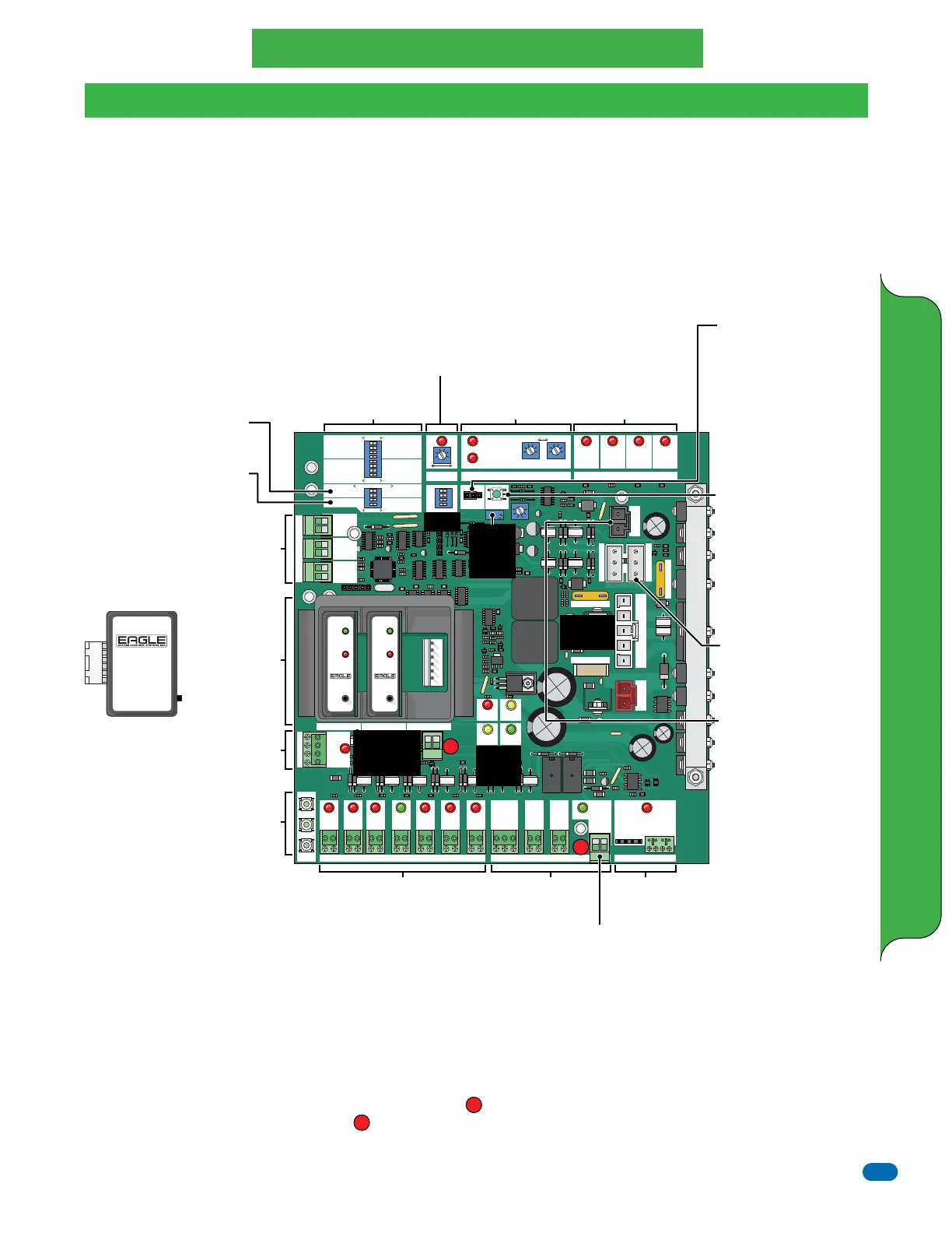
Feature Selector
See next page
M/S Phase
DO NOT remove jumper or
operator will NOT function.
Designates communication
between master and slave
operators only. M/S operators
can be set for the same or
opposite phase, depending on
operators communication
(can vary).
Reset Button
Press for soft reset of
operator (reset board logic).
Turns OFF activated alarm.
Try this button before
preforming a hard shutdown
of operator (turn power
switch OFF/ON) when
operator fails.
Solar Panel Connector
If using optional solar power,
use only Eagle 24 V Solar
Panels (EG-510-10 watt,
EG-515-15 watt or
EG-520-20 watt). Connect
accessories like the photocell
sensor to 24 VDC output
#12. The amp draw will be
minimized when the gate
operator is not in use
(overnight) saving battery
power (Power Save Mode).
Close Timer - See page 24
Reverse Sensor
See page 24
Limit Switches
See page 22
Global Inputs
Descriptions - See page 25
Wiring Accessories - See page 26
Outputs
See page 24
Open Delay Master/Slave
See next page and page 27
Power Fail Operation
See next page
Master/Slave
See page 27
3-Button Station
Cycles Operator
Radio
Receiver
See page 25
Eagle Plug-In
Loop Detector
Connections
See instructions
on the Eagle loop
detectors when
using them.
In-Ground Loop Wires
Connection
Connect in-ground loop wires
to corresponding loop
detector Only when using
Eagle Plug-In Loop Detectors.
Loop Detector
EG167
Sensitivity
Indicators
Push & hold Reset/Sen. button
LED will blink from 1 to 4 times. Release
button upon reaching desired sensitivity.
1 = Very Low, 2 = Low,
3 = Normal, 4 = High
To change from inductive loop to
mini-loop- see instructions.
Green - Steady indicates power
Fast blink - Shorted loop
Slow blink - Open loop
Red - Detect Indicator
EG167
Power
Detect
Reset
Vehicle
Detector
EG167
Power
Detect
Reset
Vehicle
Detector
Eagle Plug-In
Loop Detector
Automatically adjusts for
proper sensitivity. Eagle
brand are designed for
“Fail-Safe” operation.
24 VDC Output
“Remains ON”
Power Save Mode
See below
24 VDC Output
“Minimizes”
Power Save Mode
See below
See
page 21
Power
Indicator
LEDs
See page 21
5-Pin Primary
Connector
See page 21
Limit Switch Connector
MUST be plugged in for
operator to set open and
close limits on gate.
Secondary
ERD Sensor
“Fine Tune”
Adjustment
See page 24
Pre-Installation Battery Charging
Prior to installation, make sure the batteries are fully charged. The Battery Pack has been fully charged at the factory, but the batteries will get
depleted over time and charging may be necessary before installation. The batteries WILL NOT CHARGE unless the 5-pin primary plug is
connected to the Diamond DC board and 115 VAC input power has been connected to the gate operator. The night before installation, connect
the gate operator AC power wires (See page 22) to a reliable 115 VAC power source or an adequate portable generator in the field/job site and
plug in the 5-pin primary plug (White Plug) into the 5-pin primary connector on the board. Charging takes place automatically if the batteries
require it an will be fully charged by morning. The power indicator LEDs will let you know what is taking place with the operator. Disconnect
115 VAC input power and remove 5-pin primary plug from Diamond DC board before installation.
Power Save Mode
The Diamond DC board automatically goes into POWER SAVE MODE when AC power is NOT present (operator is powered by batteries ONLY)
OR the gate operator has not been active for 30 seconds when using ONLY battery power (solar-only power). This increases the number of
gate cycles when using ONLY battery power. The board will go to “Sleep” after 30 seconds of inactivity to conserve power. It appears
non-functioning at this time (all LEDs are OFF) until a command is received by the radio receiver, reset button, on-board 3-button station or an
exit open loop. Two 24 VDC power accessories outputs are available. (#12 - 24 VDC) MINIMIZES the power draw in POWER SAVE MODE
when the gate operator is not in use (overnight). (24 VDC Output - located below the plug-in exit loop detector on the board) REMAINS ON
and draws full power continuously. It is NOT recommended using this output when using “Solar-Only” power.
2
2
1
1
DIAMOND DC BOARD ADJUSTMENTS AND WIRING
SLAVE
OPEN LEFT
BRAKE OFF
REVERSE LOOP NO
ONE PASS OFF
STOP-REVERSE OFF
ALARM-RESET OFF
CLOSE TIMER OFF
Diamond DC Board
Diamond DC Board ONLY