84 Eaton 9355 UPS (10/15 kVA) User’s Guide 164201594—Rev H0
Table 9. IRC Wire Terminations (Continued)
IRC Terminal Function Remarks
J2-10 NC
Alarm modeJ2-11 COM
J2-12 NO
Maximum contact rating: 250 Vac, 30 Vdc @ 5A; Wire range: 16 24 AWG
66..22..55 LLaannSSaaffee PPoowweerr MMaannaaggeemmeenntt SSooffttwwaarree
Each Eaton 9355 UPS ships with LanSafe Power Management Software and an interface cable. To begin
installing LanSafe software, see the instructions accompanying the Software Suite CD.
NOTE Use only the supplied communication cable to connect the UPS to your computer.
LanSafe software provides up-to-date graphics of UPS power and system data and power flow. It also gives
you a complete record of critical power events, and it notifies you of important UPS or power information. If
there is a power outage and the Eaton 9355 UPS battery power becomes low, LanSafe software can
automatically shut down your computer system to protect your data before the UPS shutdown occurs.
66..33 CCoonnttrrooll TTeerrmmiinnaallss
The cables should be connected to the control terminals with a mating connector. Input and output terminals
have a functional isolation from terminal to terminal. They are connected to the UPS chassis through individual
1 MW resistors.
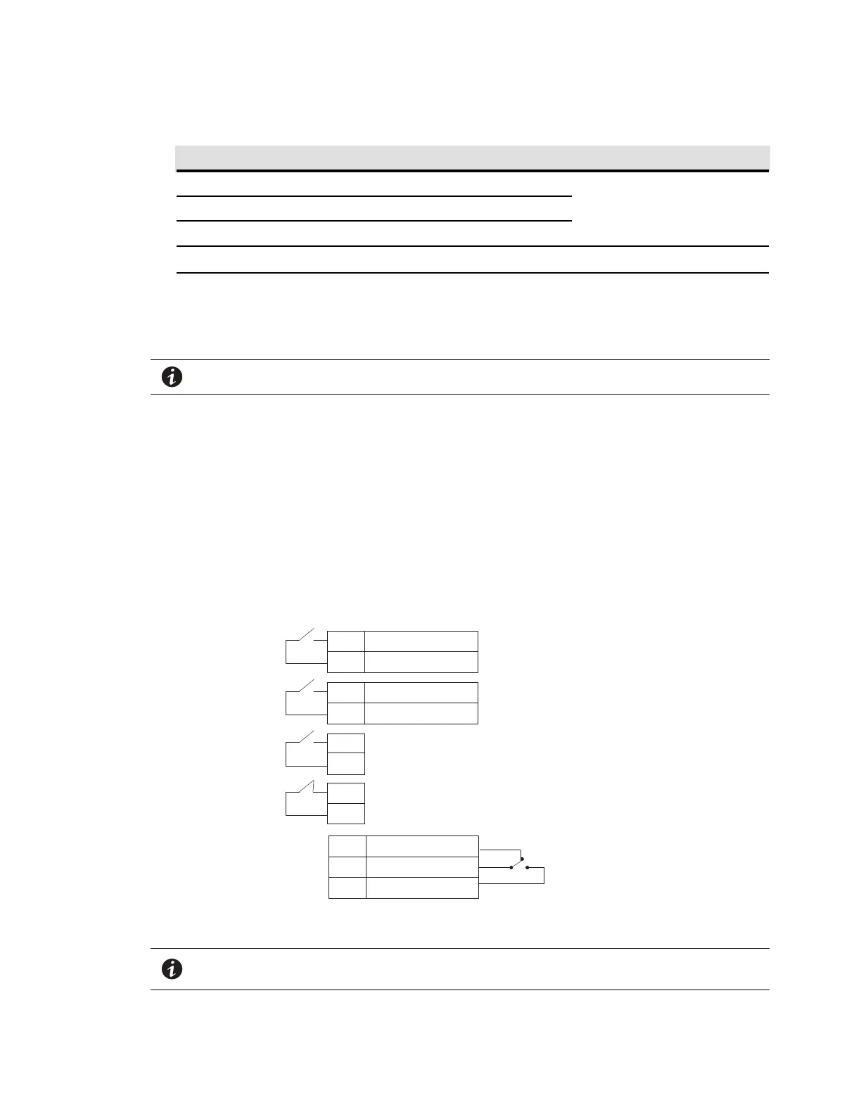
Figure 71. External Control Terminal Connections
+ Polarity
– Polarity
2
1
+ Polarity
– Polarity
2
1
2
1
2
1
Signal Input 1 (programmable)
Signal Input 2 (programmable)
REPO Normally Open
REPO Normally Closed
Normally Open
Normally Closed
1
2
Common
3
Relay Output
UPS
Connectors
NOTE If using a semiconductor switch type, pay attention to the proper polarity. A relay or
other mechanical control is preferred.
Communication

 Loading...


