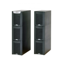
Note: Diagram illustrates one out of two battery strings
(2-high configuration) or four battery strings
(3-high configuration).
Battery symbol shown represents a battery
tray assembly containing 8 batteries.
Notes:
1. Use only 90 C-Rated copper wire, minimum wire size is based on 120/208 full load ratings applied to Nation Electrical Code (NEC ) Table 310.15(B)(16). Code may
require a larger AWG size than shown in this table because of termperature, number of conductors in the conduit, or long service runs. Follow local requirements.
2. Per NEC article 300-20(A) for ferrous metal raceways, all three-phase conductors must be run in the same conduit. Neutral and ground must be run in the same
conduit as the phase conductors.
3. Conduit is sized to accommodate one neutral conductor the same size as the phase conductor and one ground conductor.. If two neutral conductors or an oversized
neutral conductor are to be installed, check the size of the conduit needed to accommodate the extra wire or size and use that conduit size in place of the conduit
size listed. Conduit sizes were chosen from NEC table C1, type letters RHH, RHW, RHW-2, TW, THW, THHW, THW-2.
External Battery Connector
(Plug Connection)
Note: Up to four Extended
Battery Modules can be added.
- Customer
Supplied
- Factory
Supplied
- Factory
Options
Key:
208V 60 Hz
208V 60 Hz
Output
UPS Input Breaker
480V or 600V 60 Hz input

 Loading...