Page 2-1
IL17569
Effective June, 2001
2 QUICK START
2.1 Introduction
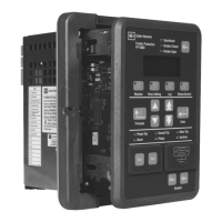
The purpose of a Quick Start section is to provide a minimal over-
view of what it takes to operate the FP-5000. This perspective is
useful as either providing the framework for learning the FP-5000
more thoroughly or for actually handling a simple application. The
FP-5000 is approachable at a variety of levels. Significant results
may be obtained with basic knowledge, yet the FP-5000 is powerful
enough to handle the most difficult and involved of applications.
Use this Guide to begin performing basic metering functions
quickly, without reviewing complete instructions provided in the
User’s Manual. To more fully understand the wide array of features
offered by your FP-5000, it is strongly recommended that operators
read the entire User’s Manual. Following initial power-up of the FP-
5000, the displayed “Meter Menu” values may not be what is
anticipated for your specific system. The unit must first be
programmed with “General Setup” information relating to your
electrical system.
CAUTION
THE FP-5000 MUST BE SET FOR THE PARTICULAR APPLICA-
TION BEFORE ENERGIZING THE ELECTRIC POWER SYSTEM.
2.2 Initial Checks
Your FP-5000 will either come pre-installed in a panel or as a
separate FP-5000 component assembly package including an
“Outer Chassis” assembly and an “Inner Chassis” assembly
containing the major portion of the operating electronics. Follow
Section 7 “Startup” if a review of the installation is required.
2.3 Standard Mounting
The FP-5000 is shipped with the Outer Enclosure assembled with a
backing plate between the enclosure housing box and the front
latching frame. This factory assembled outer chassis allows for
panel thickness variations, minor panel distortions and has relaxed
panel cutout tolerance requirements for easy faster panel mounting.
The panel footprint outline is equivalent to the Cutler-Hammer
DT3XXX and MP3XXX draw-out designs. However it differs from
most Cutler-Hammer IQ style panel mounts in that:
• The panel cutout is slightly larger.
• The enclosure is mounted from the front user side of the panel.
• Four mounting studs/nuts are used for panel mounting instead of
10 mounting screws.
The standard panel cutout is shown in Figure 2-1.
Please refer to Section 6.1 for mounting details.
For IQ cutout retrofit see Section 6.2.
Figure 2-1. FP-5000 Standard Panel Cutout
2.4 Wiring
2.4.1 Powering the FP-5000
Power Supply control power is brought in on TB 101/102. Nominal
input range is either:
• 100–120V AC
• 48–125V DC
Terminal 101 is positive DC or Hot on AC with 102 being the common
DC return or the AC neutral. With control power applied, the FP-
5000 may be programmed and minimal functionality may be
verified.
2.4.2 Typical Application Wiring
CAUTION
WIRING PROCEDURES MUST BE PERFORMED ONLY BY
QUALIFIED PERSONNEL WHO ARE FAMILIAR WITH THE FP-
5000 AND ITS ASSOCIATED ELECTRICAL EQUIPMENT. EN-
SURE THAT INCOMING POWER SOURCES ARE TURNED OFF
AND LOCKED OUT PRIOR TO PERFORMING ANY ELECTRICAL
WORK. FAILURE TO DO SO MAY RESULT IN SERIOUS INJURY
OR EQUIPMENT DAMAGE.
Wiring installation for the FP-5000 must follow a suitable Wiring
Plan Drawing and conform to applicable Federal, State and Local
codes. Direct wires to the terminal blocks TB1 and TB2 must not be
larger than AWG No. 14 (without spade lugs) and no smaller than
18 AWG. TB4 for the Ct connections can support 10 to 14 AWG.
The lug screws of TB1, 2 and 4, are not captive and may be backed
out entirely for the purpose of securing a ring terminal. The
removable terminal plugs of TB3 can support direct connection of
14 to 20 AWG wires, however ferrules are recommended on the
wire termination to minimize shorting of frayed wires. The following
two figures, Figure 2-2 and Figure 2-3, show typical wiring
diagrams. Additional wiring diagrams are shown in Section 6.

 Loading...


