Page 12-13
IL17569
Effective June, 2001
Table 12.12 Trip Log Record Line-by-Line — continued
Line Display Description
20 Output Gate Status * A group of status flags detailing the state of the logic output gate driving each
output relay as well as the state of auxiliary LED at the time of the trip.
21 Logic Block Status * A group of status flags detailing the logical state of the programmable blocking
gates output at the time of the trip.
22 Logic Gate Status * A group of status flags detailing the logical state of the programmable logic
gates and timing gates at the time of the trip.
23 SYSALM Pickup * A group of status flags detailing the system alarm pickups at the time of the trip.
24 SYSALM Timeout * A group of status flags detailing the system alarm timeouts at the time of the trip.
25 Breaker Status * A group of status flags detailing the breaker state and associated alarms
at the time of the trip.
26 Ogx Input Settings * Shows the program settings of the inputs on the output logic gate that has driven
either Trip 1 or Trip 2 to the active state at the time of the trip. This can identify which
trip relay has activated.
27 Ogx Input State * Shows the state of each logic input on the output logic gate that has driven either
Trip 1 or Trip 2 to the active state.
28 Trip Test Status * A group of status flags that shows if any output relay or zone interlock output has
been forced to the active state through the test function.
29 rms Values * Show the rms values of currents and voltages, as well as the frequency, current
unbalance, and voltage unbalance at the time of the trip.
30 V&I Phasors * Shows the fundamental voltage and current phasors with magnitude
and relative phase angle.
* Indicates information available by selecting the line and pressing Enter.
12.2.3 History Log
The history log records statistics that can be gathered over time. It
is therefore useful in detecting chronic problems that occur over
time. In addition it keeps track of the number of operations and
accumulated interrupted amps, that can indicate if the breaker
needs maintenance. Each history log has a date-times stamp to
indicate when the data was last reset. Each history log can be reset
by pressing the reset button until the reset menu appears, then
selecting History Log and then choosing the correct history log to be
reset. See Section 4.13 for more information on the history log.
12.2.4 Using Waveform Data
Waveforms of all current and voltage phases are available through
the PowerNet application software. The trigger of the waveform is
automatic when the Trip 1 relay output contact activates. Using a
logging setting (see setpoint Section 5) the waveform capture can
also be triggered on the activation of the Trip 2 relay. See applica-
tions Section 8.10 and Section 5 for more information on how to set
up the waveform capture.
12.2.5 Detection of Breaker Failures
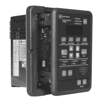
The FP-5000 can detect failures in the breaker that can be useful in
troubleshooting the system. Detectable failures include:
• Breaker failure to interrupt fault current
• Slow breaker operation time
• Breaker state alarm due to conflicting 52a and 52b contact inputs
• Open circuit detection on the trip or open coil circuit, and the close
coil circuit
Please see application Section 8.9 and setting Section 5
for more details.
12.2.6 Detection of Failed Current or Voltage Transformer
The loss of the ability to read a phase voltage or current can be
detected by using the 46 current unbalance and 47 voltage
unbalance protection alarm functions (see Section 5). If a current or
voltage transformer circuit should fail then a large unbalance of 50%
will be detected and an alarm can be raised.

 Loading...


