M-Max Series adjustable frequency drive
10 For more information visit: www.eaton.com
MN04020002E
February 2010
Block diagram
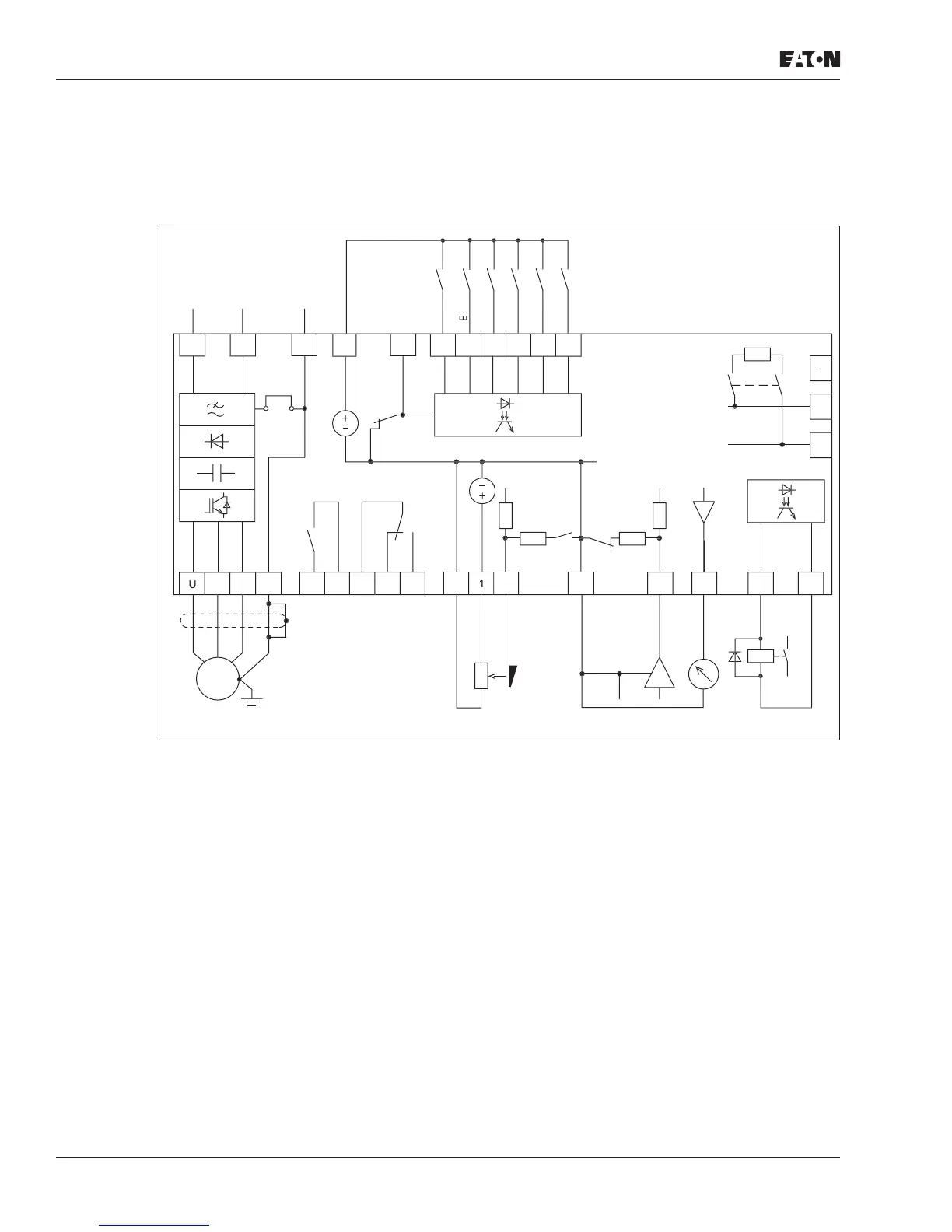
The following diagrams show all the terminals on an M-Max Series adjustable frequency
drive and their functions at the default settings.
Figure 4: Block Diagram MMX11
Note: Block diagram MMX11 has a voltage doubler connection in the internal DC link.
At a connection voltage of 1 AC 120V (115V), a motor voltage of 3 AC 230V is output.
2
~
2
2
–
1
I
I5
I
ND
I
COM
1
mA
1
1
1
l-
ff
mA
ND
1
V
12
mA
1
mA
+
2
1
L2
1 A
12
A
2
L
2
2
2
2
n
rr
r
ead
... +1
V
... +1
V
l-1
4
... 20 mA
f-
ll
-
EM

 Loading...


