M-Max Series adjustable frequency drive
20 For more information visit: www.eaton.com
MN04020002E
February 2010
Parameters
Control unit
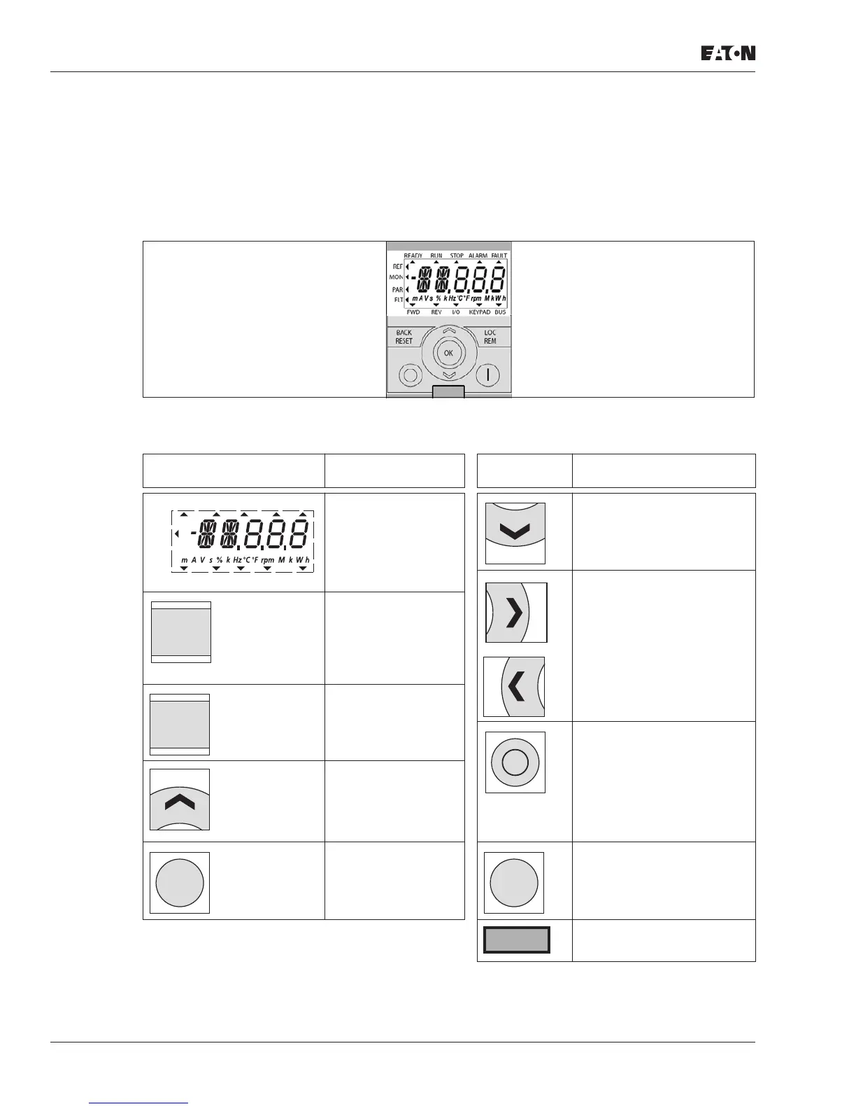
The following figure shows and indicates the elements of the M-Max’s Series
integrated control unit.
Figure 9: View: Control Unit With LCD Display, Function Keys, and Interface
Table 6: Control Unit Elements
Operating Unit
Element Explanation
Operating
Unit Element Explanation
• Backlit liquid
crystal display
(LCD)
• Plain text with
alphanumeric
characters
• Select function and
parameter
• Reduce numerical value
• Switch to individual
parameter groups
(... S4.1 - P1.1 - P2.1 - P3.1 ...)
• Select individual digits in
multi-digit display
• Acknowledge fault
message (Reset)
• Activates the
selection for the
menu levels
( flashes)
Switch between the
different control levels
(I/O – KEYPAD – BUS)
• Stops the running motor
(P6.16)
• With the menu level active
( flashing) you can load
the default settings (press
and hold the key for five
seconds). This clears the
fault memory (FLT).
• Select function and
parameter
• Increase numerical
value
• Confirm and
activate selection
(store)
• Lock display
Motor start with selected
direction of rotation (only
active in KEYPAD control
level)
Interface for communication
(Option: MMX-COM-PC)
REF
FWD REV I/O KEYPAD BUS
MON
PAR
FLT
READY RUN STOP ALARM FAULT
BACK
RESET
LOC
REM
OK
I

 Loading...


