M-Max Series adjustable frequency drive
MN04020002E
For more information visit: www.eaton.com 33
February 2010
All Parameters
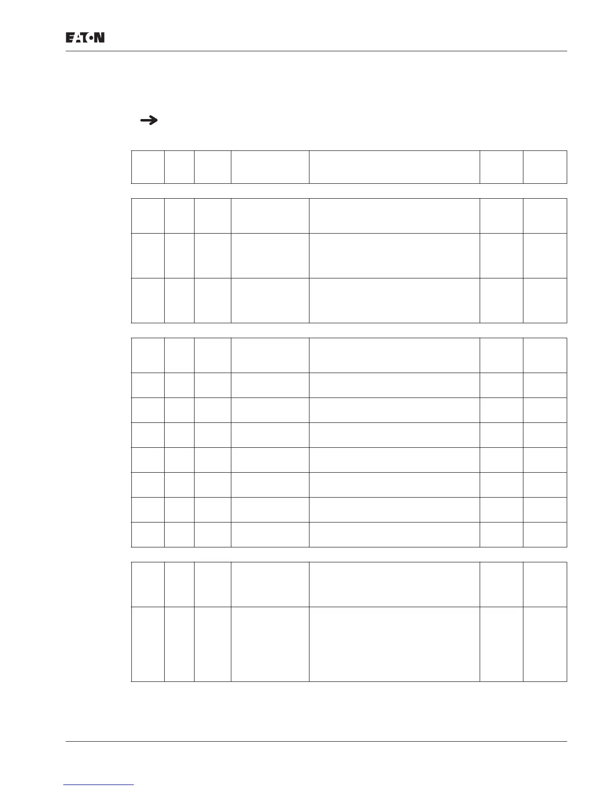
Table 11: All Parameters
When first switching on or after activating the default settings (S4.2 = 1) parameter P1.1
must be set to 0 for access to all parameters.
PNU ID
Access
Right
RUN Designation Value Range
Factory
Setting
User
Setting
Parameter Selection
P1.1 115 ✓ Parameter range 0 = All parameters
1 = Only quick configuration
parameters
1
P1.2 540 — Application 0 = Basic
1 = Pump drive
2 = Fan drive
3 = High starting torque
0
P1.3 1472 — Factory setting
(WE),
Country-specific
(enabled and visible only in the quick
start wizard)
0 = EU (50 Hz-based defaults)
1 = USA (60 Hz-based defaults)
0
Analog Input
P2.1 379 ✓ AI1, Signal range (DIP switch S2)
0 = 0V/0 mA
1 = 2V/4 mA
0
P2.2 380 ✓ AI1, minimum
value
–100.00 – 100.00% 0
P2.3 381 ✓ AI1, maximum
value
–100.00 – 100.00% 100
P2.4 378 ✓ AI1, filter time
constant
0.0 – 10.0s 0.1
P2.5 390 ✓ AI2, Signal range (DIP switch S3)
Like P2.1
3
P2.6 391 ✓ AI2, minimum
value
–100.00 – 100.00% 0
P2.7 392 ✓ AI2, maximum
value
–100.00 – 100.00% 100
P2.8 389 ✓ AI2, filter time
constant
0.0 – 10.0s 0.1
Digital Input
P3.1 300 ✓ Start/stop logic 0 = DI1 (FWD), DI2 (REV)
1 = DI1 (START), DI2 (REVERSE)
2 = DI1 (Start pulse), DI2 (Stop pulse)
3 = DI1 (FWD), DI2 (REV) and REAF
3
P3.2 403 ✓ Start signal 0 = Deactivated
1 = DI1
2 = DI2
3 = DI3
4 = DI4
5 = DI5
6 = DI6
1

 Loading...


