M-Max Series adjustable frequency drive
MN04020002E
For more information visit: www.eaton.com 13
February 2010
Operation
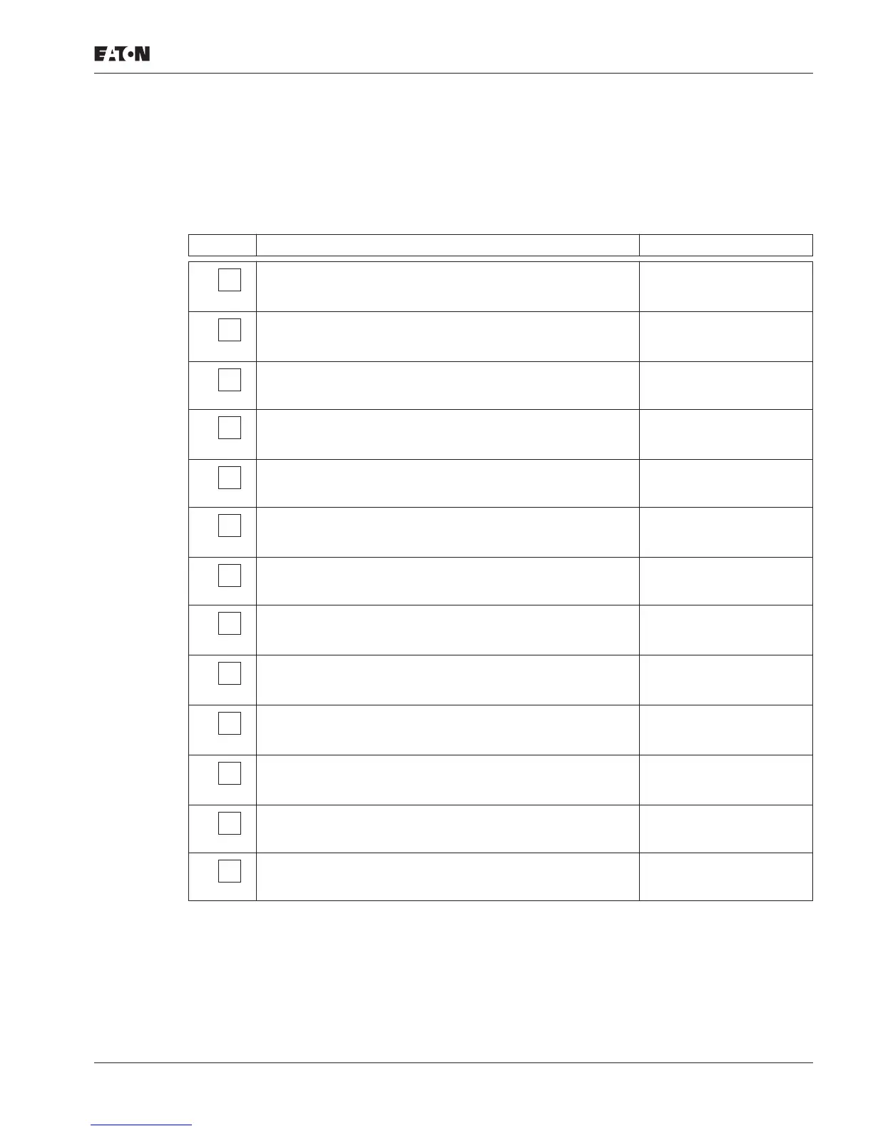
Checklist for commissioning
Before placing the adjustable frequency drive into operation, make sure to check the following
(checklist)
:
No. Activity Note
1 Installation and wiring have been carried out in accordance
with the corresponding installation instructions
( IL04020001E).
2 All wiring and line section leftovers, as well as all the tools
used, have been removed from the adjustable frequency
drive’s proximity.
3 All terminals in the power section and in the control section
were tightened with the specified torque.
4 The lines connected to the output terminals of the adjustable
frequency drive (U/T1, V/T2, W/T3, R+, R–) are not short-
circuited and are not connected to ground (PE).
5 The adjustable frequency drive has been earthed
properly (PE).
6 All electrical terminals in the power section (L1, L2/N, L3, U/T1,
V/T2, W/T3, R+, R–, PE) were implemented properly and were
designed in line with the corresponding requirements.
7 Each single-phase of the supply voltage (L1, L2, L3) is
protected with a fuse.
8 The adjustable frequency drive and the motor have been
adjusted for the corresponding line voltage (
section “Rated
operational data on the nameplate,” Page 4).
9 The quality and volume of cooling air are in line with the
environmental conditions required for the adjustable
frequency drive.
10 All connected control lines comply with the corresponding
stop conditions (e.g., switch in OFF position and set point
value = zero).
11 The parameters that were preset at the factory have been
checked with the list of parameters (
section “List of
parameters,” Page 30).
12 The effective direction of a coupled machine will allow the
motor to start.
13 All emergency switching off functions and safety functions are
in an appropriate condition.

 Loading...


