M-Max Series adjustable frequency drive
22 For more information visit: www.eaton.com
MN04020002E
February 2010
Display unit
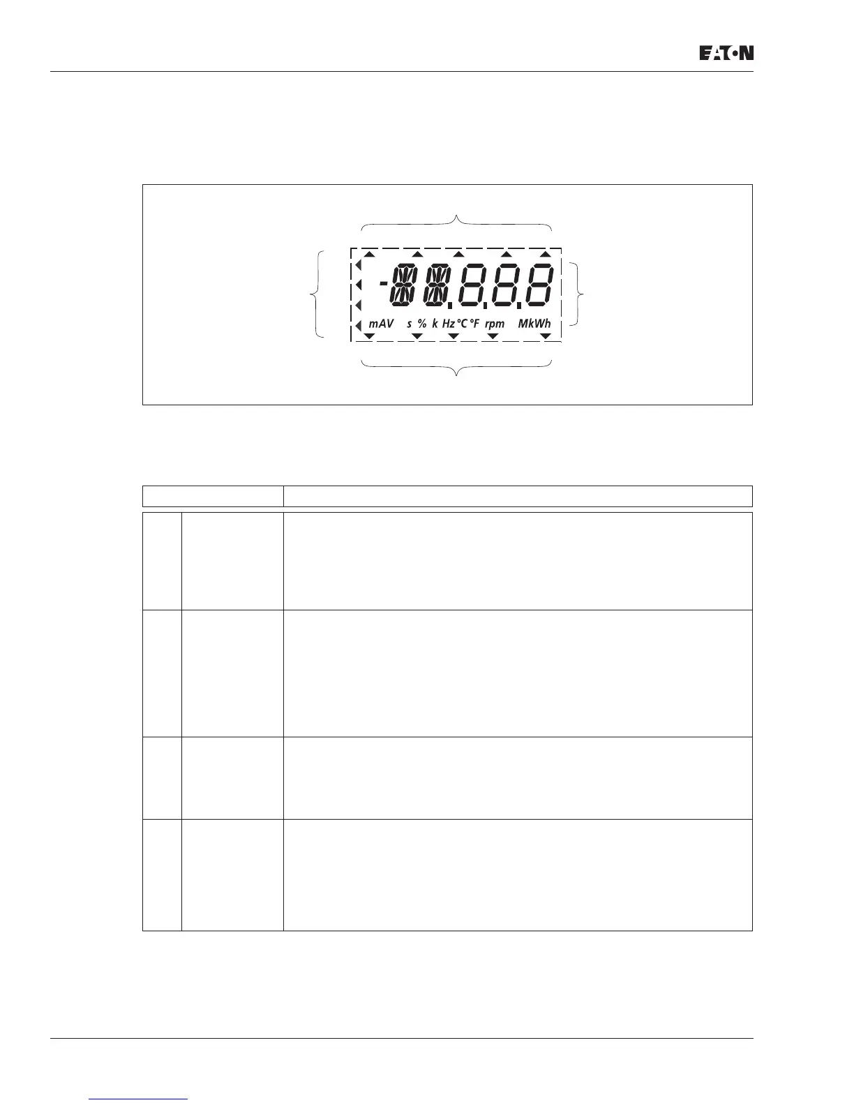
The following shows the display unit (LCD display with all display elements)
Figure 10: LCD Display (Areas)
The display unit consists of a backlit liquid crystal display (LCD). It is divided into four areas:
Table 7: Areas of the LCD Display
Area Description
Status display The arrowheads () on the top border show information regarding the drive:
• READY = Ready to start
• RUN = Operating notification
• STOP = Stop, stop command activated
• ALARM = Alarm message activated
• FAULT = The drive has been stopped due to an error message.
Plain text
display
Two 14- and three 7-segment blocks for displaying:
• AL = Alarm message
• F = Error messages
• M = Measurement value (operating data)
• P = Parameter numbers
• S = System parameter
•
- = Anticlockwise field of rotation (REV)
The respective units of measurement are displayed in the bottom line.
Menu level The arrowhead () shows the selected main menu:
• REF = Set point input (Reference)
• MON = Operational data indicator (Monitor)
• PAR = Parameter levels
• FLT = Fault log (Fault)
Control
commands
The arrowhead () points to the selected rotating field direction and the
active control level:
• FWD = Clockwise rotating field (Forward Run)
• REV = Counterclockwise rotating field (Reverse Run)
• I/O = Via control terminals (Input/Output)
• KEYPAD = Via control unit
• BUS = Via field bus (interface)
REF
FWD REV I/O KEYPAD BUS
MON
PAR
FLT
READY RUN STOP ALARM FAULT

 Loading...


