INSTALLATION
EATON BladeUPS
®
(12 kVA) User's Guide S 164201649 Rev 4www.eaton.com/powerquality
23
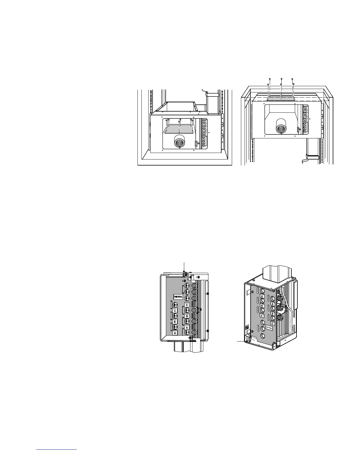
3. Remove the six screws on the conduit landing plate and retain. Remove the plate
and retain. See Figure 7.
Bottom Entry Rack Top Entry Rack
Figure 7. Removing the Conduit Landing Plate
4. Use a Greenlee
®
punch to provide one or more holes in the conduit landing plate
to accommodate the input and output wiring from the utility to the
BladeUPS Bar.
Replace the conduit landing plate.
5. Connect the input, output, and ground wires to the BladeUPS Bar terminal block
according to Figure 8 and Table 2. Route the three input phases and the input
neutral through the mounted or loosened ferrite assembly (see Figure 6).
Ground
Ground
Top Entry
Terminal Block
Bottom Entry
Terminal Block
Figure 8. BladeUPS Bar Terminal Block

 Loading...


