INSTALLATION
EATON BladeUPS
®
(12 kVA) User's Guide S 164201649 Rev 4www.eaton.com/powerquality
43
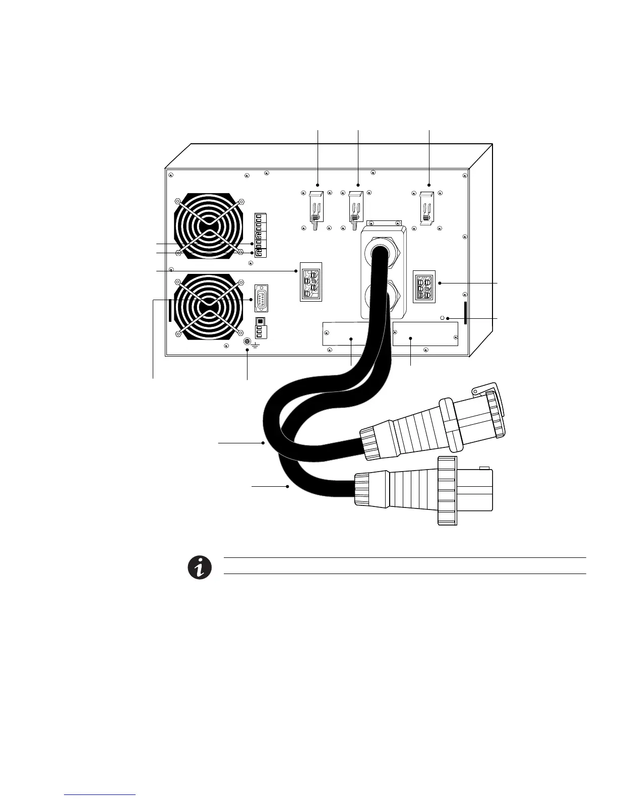
Load
Connector
Breaker
Input
Breaker
Battery
Breaker
Load
Connector
REPO (NC)
REPO (NO)
Communication Port
Ground
Bonding
Screw
UPS
Battery
Connector
X-Slot Communication Bay 1
X-Slot Communication Bay 2
Output Power Cord
Input Power Cord
Surge
Protection
(leave
installed)
Figure 32. BladeUPS Module Rear Panel (Standalone UPS Shown with IEC 309-60A Output Power Cord)
NOTE The load connector breaker controls the load connector only, not the output power cord.
Parallel UPS Installation
Follow the appropriate procedure for the type of parallel configuration.
S Follow the procedure “New Multiple Parallel UPS Installation” on page 44 if you
are installing multiple UPSs in a new parallel configuration.
In this case, two blue terminating plugs are supplied with each UPS. None of the
Powerware Hot Sync CAN Bridge Cards contains a Jumper J7.

 Loading...


