INSTALLATION
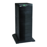
EATON BladeUPS
®
(12 kVA) User's Guide S 164201649 Rev 4www.eaton.com/powerquality
60
15. Confirm the selection. Press and hold the button for three seconds, until the
UPS stops beeping.
Verify that the indicator illuminates solid, indicating that the UPS is operating
normally and any loads not connected through the load connector are now
energized.
If the indicator is flashing, do not proceed until all alarms are clear. Check the
UPS status from the front panel to view the active alarms. Correct the alarms and
restart if necessary.
The UPS should be in Normal mode. By default, Normal mode operates on the
High Efficiency setting (see “Normal Mode” on page 67).
16. To energize a load connected through the load connector, switch the load
connector circuit breaker to the ON () position.
17. Press the
ESC
button until the Start screen appears.
18. If optional EBMs are installed, see “Configuring the UPS for EBMs” on page 74
to set the number of installed EBMs.
19. To change any other factory-set defaults, see “Operation” on page 63.
NOTE Eaton recommends setting the Date and Time and the Start screen.
20. If you installed an optional REPO, test the REPO function:
Activate the external REPO switch. Verify the status change on the UPS display.
Deactivate the external REPO switch and restart the UPS.
21. See “Updating the UPS Firmware” on page 98.
NOTE The batteries charge to 80% capacity in less than 5 hours. However, Eaton recommends that the
batteries charge for 48 hours after installation or long-term storage.
Parallel System Initial Startup
To start up a parallel (or parallel-ready) system:
NOTE Verify that the total equipment ratings do not exceed the parallel system capacity to prevent an
overload alarm.
1. Verify that all UPS circuit breakers are in the OFF (O) position.
NOTE The load connector breaker controls the load connector only, not the output power cord.
2. Switch on utility power where the UPS is connected.
3. Remove the breaker ties from the circuit breakers.
4. Switch the UPS input circuit breaker on each UPS to the ON (
) position.
5. Wait for the front panel display on each UPS to illuminate.
The
indicator flashes on each UPS.

 Loading...


