Installation
16 S801+ Soft Starter MN03900002E—November 2012 www.eaton.com
Typical Control Wiring Diagrams
Each diagram illustrates a typical wiring scheme for the
options described. The additional components shown on the
diagrams are not included, but may be purchased from
Eaton.
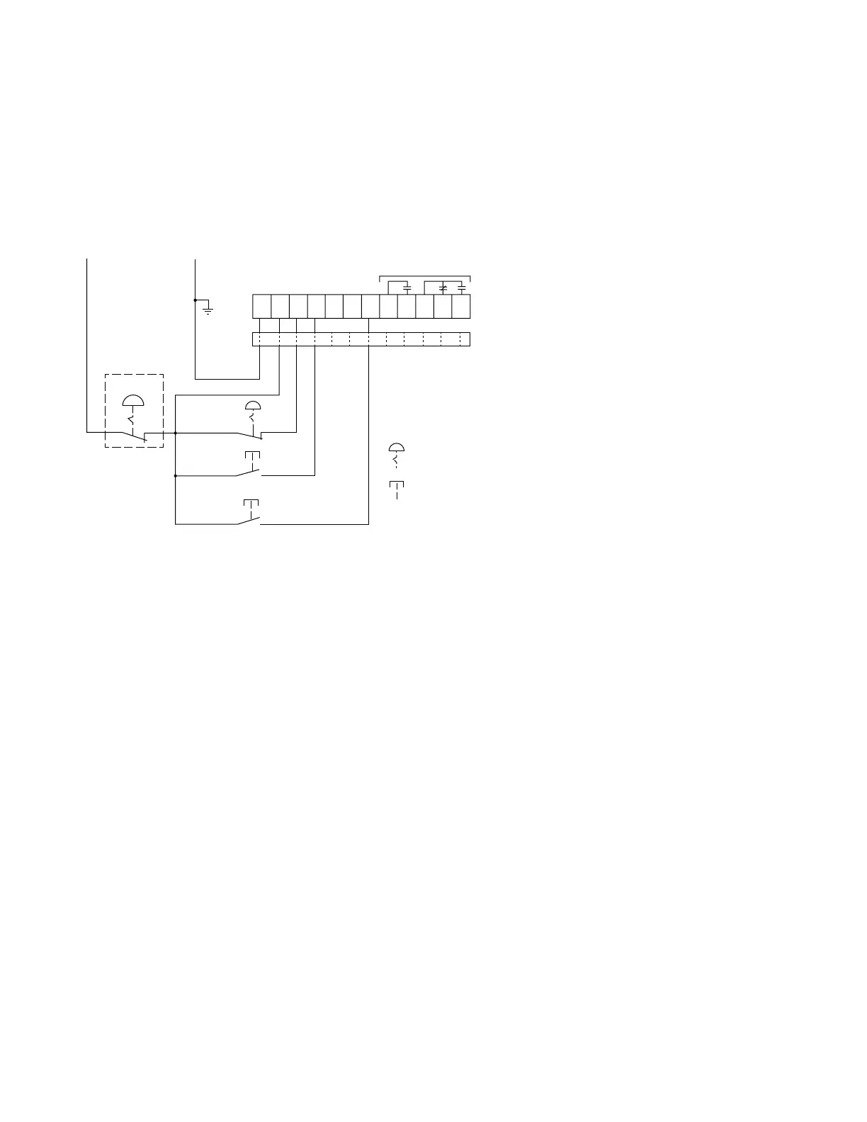
Basic Connection Diagram for 3-Wire Pushbutton
Notes
1. A minimum wire of 14 AWG (2.5 mm
2
) should be used
between the 24 Vdc control power supply and the
control terminal block.
2. See Using an Auxiliary Relay section below if it is desired
to use a relay instead of an indicating lamp for terminals
13, 14, 95, 96 and 98.
3. 120 Vac may be applied to terminals 13, 14, 95, 96,
and 98.
4. Add ferrite, Fair-Rite #0446176451 to DC Power Leads
and Control I/O Leads (all through one ferrite) at S801+.
5. Auxiliary relays: 3 amps at 120 Vac or 24 Vdc, 10 amps
max. (resistive) switching.
E Stop
Start
(+) Us 24 Vdc ( ) Us
Reset
Stop
Maintained
Momentary
Ferrite
Aux Relays
-24V
+24V
Permissive
Start
Jog
Disable Ovld
Reset
98 969514134321P+

 Loading...


