EasyManua.ls Logo

EB TECHNOLOGY START-S1XL v2 - User Manual

EB TECHNOLOGY START-S1XL v2
64 pages
Go to English
Print Icon
To Next Page IconTo Next Page
Loading...
START-S1XLver2_290415_VXX11 _IT www.ebtechnology.it www.nologo.info
Centrale monofase per 1 motore 230 Vac.
Cancelli scorrevoli, porte basculanti, serrande.
3 velocità di rallentamento, apprendimento tempi automatico,
4 modi di funzionamento, gestione codici radio integrato.
START-S1XL v2
Versione Radio Integrata
100%
ITALY
Versione Radio Integrata
-16-
-17-
-1-
-2-
-3-
-4-
-5-
Contatto pulito
230 Vac
230 Vac
LAMPEGGIANTE
Com MOT / LAMP
MOT APRE
-6-
MOT CHIUDE
M
AP
CH
COM
-7-
-8-
-9-
-10-
-11-
+ Antenna
Comune e calza ant.
12 Vac
12 Vac / + 12Vdc
- 12Vdc, Comune
-12-
CHIUDE / STOP
-13-
-14-
FOTO / ANEMOMETRO
APRE / START
-15-
BUS-DATI
Alim OUTAlim
TX
RX
N.C.
N.A. N.A.
DIP 3B
ON
DIP 3B
OFF
Fotocellule attive
solo in chiusura
2002/95/EC
Selezione AC/DC tramite JUMPER J1
Vedi riquadro sotto-riportato
JUMPER J1
AC - 12 Vac
mors 9-10
DC - 12 Vdc
mors 10-11
Alimentazione ACCESSORI
JUMPER J1
Per passare da spia ssa a lampeggiante e vicevera, occorre
semplicemente tenere premuto il pulsante P, durante la manovra di
chiusura, fi no a quando il Led non lampeggia.
Contatto pulito
Per una corretta installazione
del lampeggiante fare riferimento al Par. 1.2
Question and Answer IconNeed help?

Do you have a question about the EB TECHNOLOGY START-S1XL v2 and is the answer not in the manual?

EB TECHNOLOGY START-S1XL v2 Specifications

General IconGeneral
BrandEB TECHNOLOGY
ModelSTART-S1XL v2
CategoryControl Unit
LanguageEnglish

Summary

Installation and Scheme of the Control Unit

Terminal Connections Overview

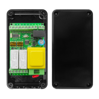
Detailed breakdown of terminal functions and connections for the control unit.

Jumper J1 Configuration

Explanation of settings for AC 12 Vac and DC 12 Vdc power supply selection.

DIP Switch Settings

Guidance on configuring DIP switches for various operational modes.

Functions and Adjustments

Standard and Anemometer Version Setup

Steps to activate and configure Standard and Anemometer operating modes.

Additional Functions and Modes

Man Present and Central Open;Close Setup

Instructions for activating and configuring 'Man Present' and Central Open/Close modes.

Operational Mode Descriptions

Overview of Operating Modes

Explanation of different operational modes like Standard, Man Present, and Anemometer.

Mode Programming with DIP Switches A & B

Programming Configurations A, B, C, D

Details on programming operational modes using DIP switches A and B.

Advanced Mode Programming

Programming Modes UP, AN, AN-1

Configuration for UP, AN, and AN-1 operational modes.

ACC Mode Programming

Central Locking Programming

Specific programming for the ACC (Central Locking) mode.

Remote Control Operations

Cancelling Stored Remote Control Codes

Procedure to erase previously memorized remote control codes from the unit.

Activating Remote Control Code Reception

Steps to enable the receiver to manage fixed and rolling codes.

Remote Control Code Memorisation

Programming New Remote Control Codes

Instructions for programming new remote control codes for OPEN and CLOSE commands.

Scheme and Symbol Reference

Remote Control Channel Functions

Explanation of how remote control channels map to OPEN and CLOSE commands.

START Step-by-Step Command

Details on the 'START step by step' command and its associated symbols.

Programming and Settings

Working Time Program Configuration

Procedure to set custom working times for gate operations.

Programming Settings and Lights

Cancelling Working Time Programs

How to revert working time programs to standard default values.

Fixed or Flashing Light Modes

Instructions for setting the indicator light to fixed or flashing.

BUS Data System Connection

BUS L2 Installation Example

Illustrative example of connecting multiple units via the BUS L2 system.

Declaration of CE Conformity

Compliance with EC Directives

Product compliance statement regarding key European Community Directives.