Wiring_ GTA116e-P_r1a Page 1 of 1
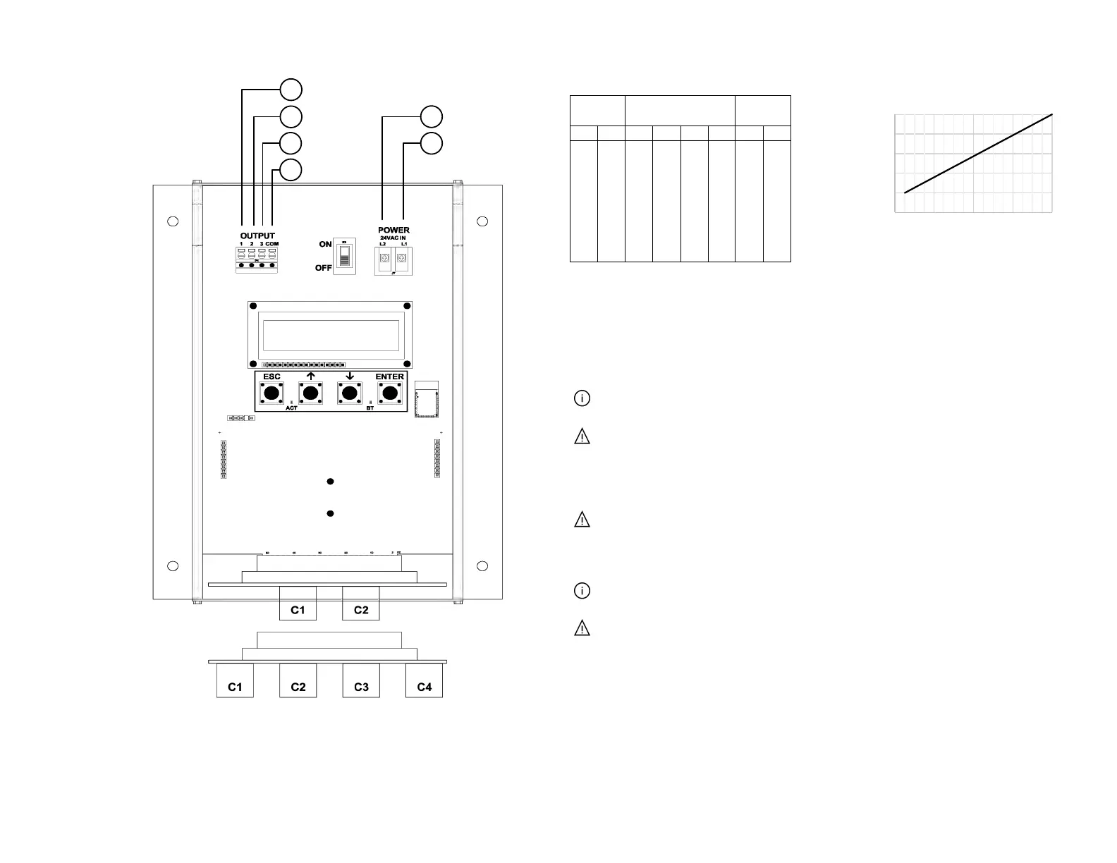
10
12
14
16
18
20
0 4 8 12 16
V-A
Total Number of Sensor Nodes
V-A REQUIREMENT @ 24 VAC
INSTRUCTIONS TO INSTALLER:
1. Mount the transmitter in a location where all probe cables can reach the receptacles of the
transmitter. Provide a weatherproof enclosure (by others) and mount away from direct sunlight when
outdoor mounting is required.
2. Connect the sensor probes to the transmitter. Although probes are “plug and play” and connections
to specific receptacles are not required, it is recommended that probes are connected Probe 1 to
receptacle C1, Probe 2 to receptacle C2, etc. Probe numbers are indicated on each cable hang tag.
Cables have an FEP plenum rated jacket that are UV tolerant and suitable for operation over the
entire operating temperature range of the device.
Sensor probe plugs are keyed and NOT twist-lock. Align the key and push the plug onto the
transmitter receptacle. Twisting may damage the connector pins.
3. Select a 24 VAC transformer that provides 22.8 to 26.4 VAC during operation. Refer to the chart
above to optimize the transformer size or size the transformer for 20 V-A for each measurement
location.
Multiple transmitters wired to a single transformer must be wired “in-phase” (L1 to L1 and L2 to L2).
4. If analog output signals are used, continue to step 5, otherwise skip to step 6.
5. Connect each analog output signal required to the host B.A.S. using shielded twisted-pair wire.
Properly terminate the shield (typically at the B.A.S.).
AO3 (relative humidity, enthalpy, or dew point) is only available if the /H humidify sensor option is
provided.
If twisted pair wire and/or shielded cable is not used, extraneous electrical noise can be picked up
between the transmitter and host control panel.
6. Refer to the GTA116e-P Startup Guide prior to moving the power switch to the “ON” position.
Advantage IV (A4) GTA116e-P WIRING GUIDE
2 probes x 8 sensors/probe
4 probes x 4 sensors/probe

 Loading...