CHAIN BRAKE SYSTEM
CS-501SX, CS-501SXH
501sx
42
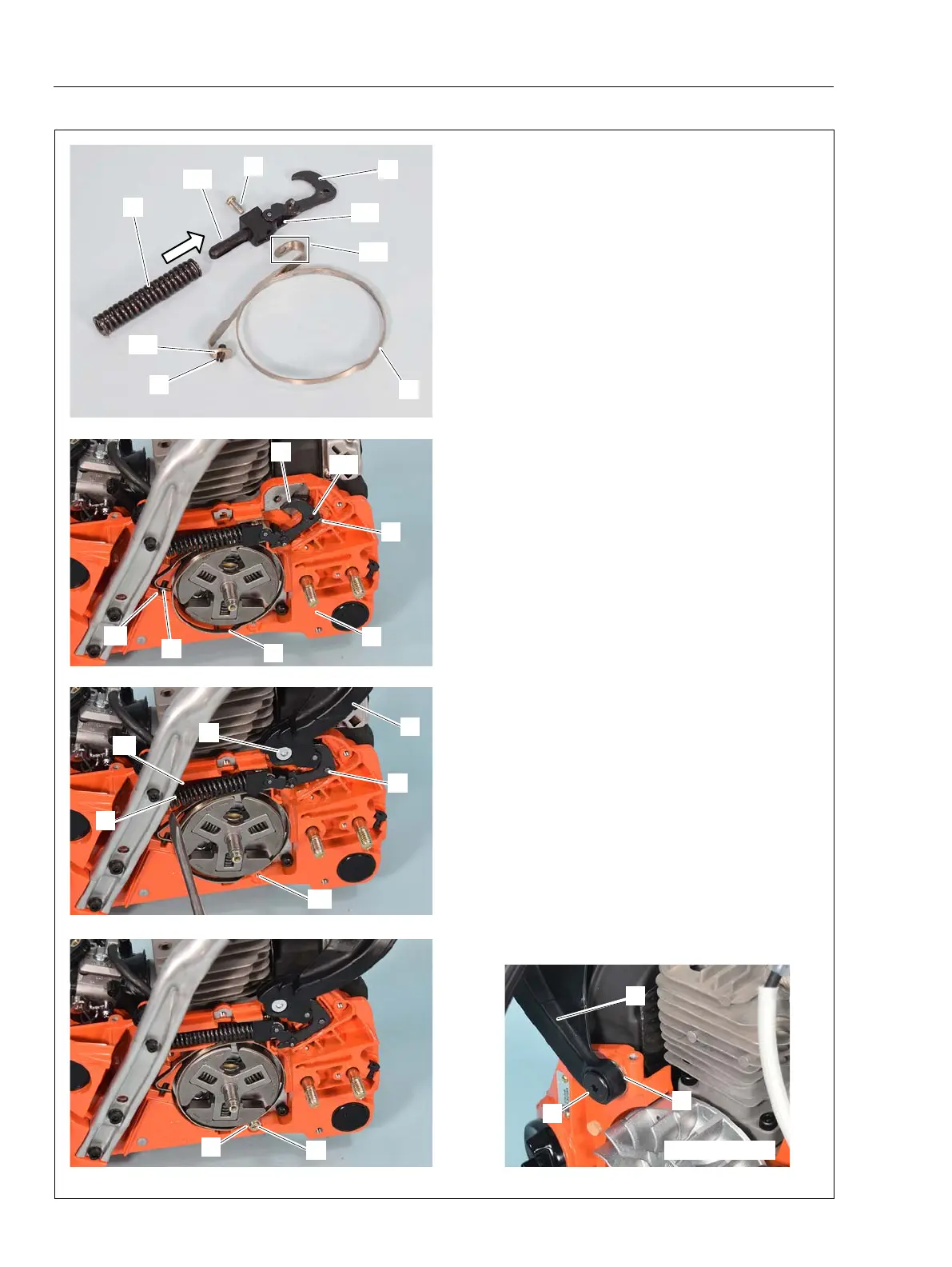
6-2 Assembling brake parts
1. Install spring pin (B) through hole (a1) of brake
band (A). Hook end (a2) of brake band (A) through
hole (c1) of brake connector (C). Tighten brake
band (A) and brake connector (C) with screw (D).
Slide in coil spring (E) to the end (c2) of brake con-
nector (C).
2. Install brake band (A) and other parts (Refer to
the above 1.) on crankcase (F) as shown. Make
sure the pin (B) in brake band (A) is engaging with
the groove (f1) of crankcase.
3. Install boss (G) through hole (c3) of brake con-
nector (C).
4. Set brake lever (H) with bolt (J).
5. Set the end of coil spring (E) on crankcase
groove (f2) by pushing with fl at head screwdriver
as shown.
6. Tighten screw (K) and washer (L) in hole (f3) of
crankcase.
7. Set brake lever (H) with bolt (M) and coller (N)
on fl ywheel side.
8. Apply molybdenum grease on entire compres-
sion spring and other friction parts.
9. Reinstall guide plate, brake cover and other
parts.
A
E
C
D
K
L
B
c1
c2
a2
a1
J
H
G
E
f3
f2
A
B
f1
G
c3
F
N
M
Flywheel side
H
C

 Loading...