Analog input signal. 0 - 10 V DC. Overvoltage protection up
to 12 V. Sampling frequency min. 100 Hz, input impedance
100 k, resolution 2.5 mV.
Digital input 2. Compatible with TTL, HC, HCT. Overvoltage
protection up to 12 V. In opened status it is on level H.
Digital input 1. Compatible with TTL, HC, HCT. Overvoltage
protection up to 12 V. In opened status it is on level H.
Semiconductor switching device, contact A and B.
Working voltage max. 60 Vdc, 42 Vac. Working current max.
240 mA. Switch impedance ON max. 2.5 ohm. Residual
current max. 1 uA.
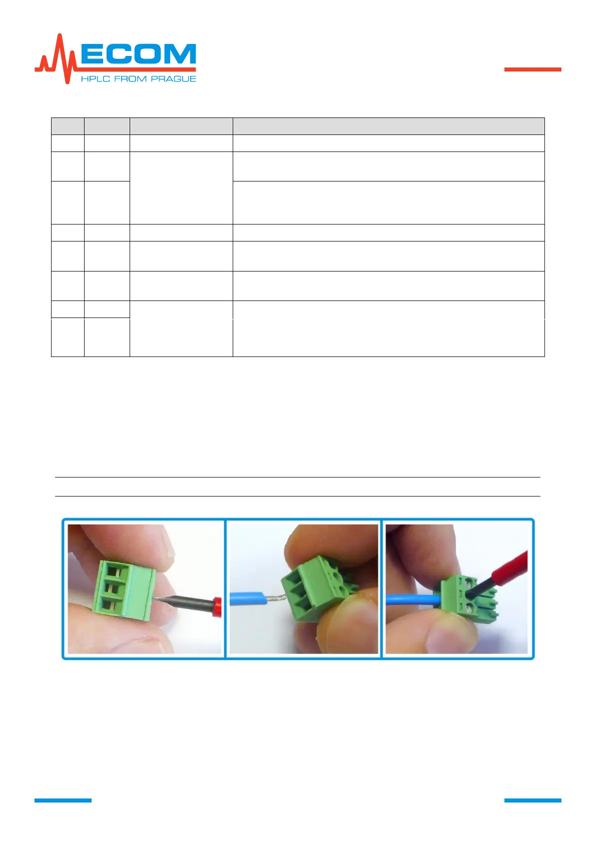
For external input/output interface IO INTERFACE are used connector blocks with screwing
contact (included in accessories).
For connecting cable to connector block, loosen the nut using small flat-tip screwdriver.
Remove isolation from the connected cable in the length of approximately 3 to 4 mm. Insert
the skinned part of cable into the place under the nut and tighten the nut. Try carefully, if the
conductor holds in the block. If the conductor is too thin, it is better to remove isolation from longer
part and bend the skinned part before inserting in the block.
Note: Connector blocks are meant for cables with section up to 1.5 mm
2
.
Diagnostics of actual IO INTERFACE status can be done in Menu/Diagnostics/Interface. For
digital inputs value OPEN (H) means opened input, high level and CLOSE (L) means closed input,
low level. For digital output is displayed OFF (for open switch) and ON (for closed switch).
Analog input, digital input 1, 2 and digital output switch can always be read through remote
control (RS232/ETHERNET).