ECP2010 / ECP2010H
47 / 68
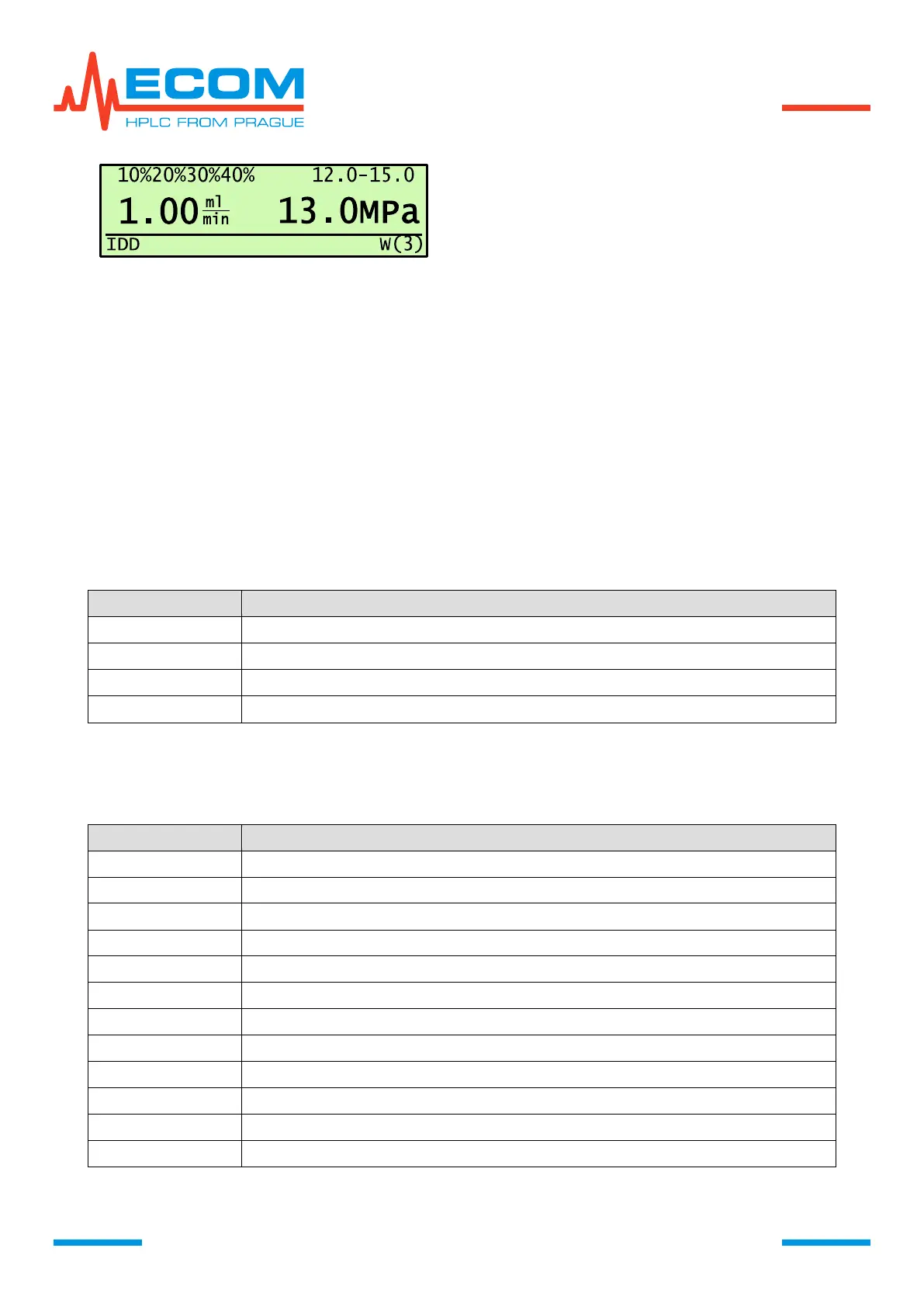
If there occurs some deviation from standard unit
behavior, on main screen displays W with a
number of warnings.
The access to descriptions and other behavior is
the same as for errors, see chapter above.
6.6.3. Power
In this menu item is displayed value of main supply voltage, nominal value is 28.0 V and it
should be within the range of 26 – 30 V.
6.6.4. Cooling
Display shows COOL. Shows rotation speed of FAN1 and FAN2 (rpm) and their
voltage (V). In pump version ECP2010 / ECP2010H is only one fan mounted, therefore for one fan
is shown NOT USED.
6.6.5. Interface
On screen is displayed IFACE. This menu item gives information about inputs/outputs of
IO INTERFACE, start signal input from injection valve (START).
STATUS OF IO INTERFACE
Status of digital inputs.
Status of digital output switch.
Status of input signal START.
6.6.6. Leakage State
On screen is displayed LEAK. Status of leakage sensor.
STATUS OF LEAKAGE SENSOR
Voltage of pump measuring sensor L (L … low current).
Voltage of pump measuring sensor H (H … high current).
Voltage of pump reference sensor L.
Voltage of pump reference sensor H.
Voltage of box measuring sensor L.
Voltage of box measuring sensor H.
Voltage of box reference sensor L.
Voltage of box reference sensor H.
Countdown to current status change L/H, H/L (Countdown).
Sensor heating – YES = heating (current High); NO = cooling- (current Low).
Pump leakage sensor YES/NO.
Box leakage sensor YES/NO.