EasyManua.ls Logo

Ecom ECP2010 - Description

Ecom ECP2010
68 pages
Print Icon
To Next Page IconTo Next Page
To Previous Page IconTo Previous Page
Loading...
ECP2010 / ECP2010H
10 / 68
3. DESCRIPTION
FRONT VIEW
No.
Description
1
Front switch.
2
Keyboard.
3a
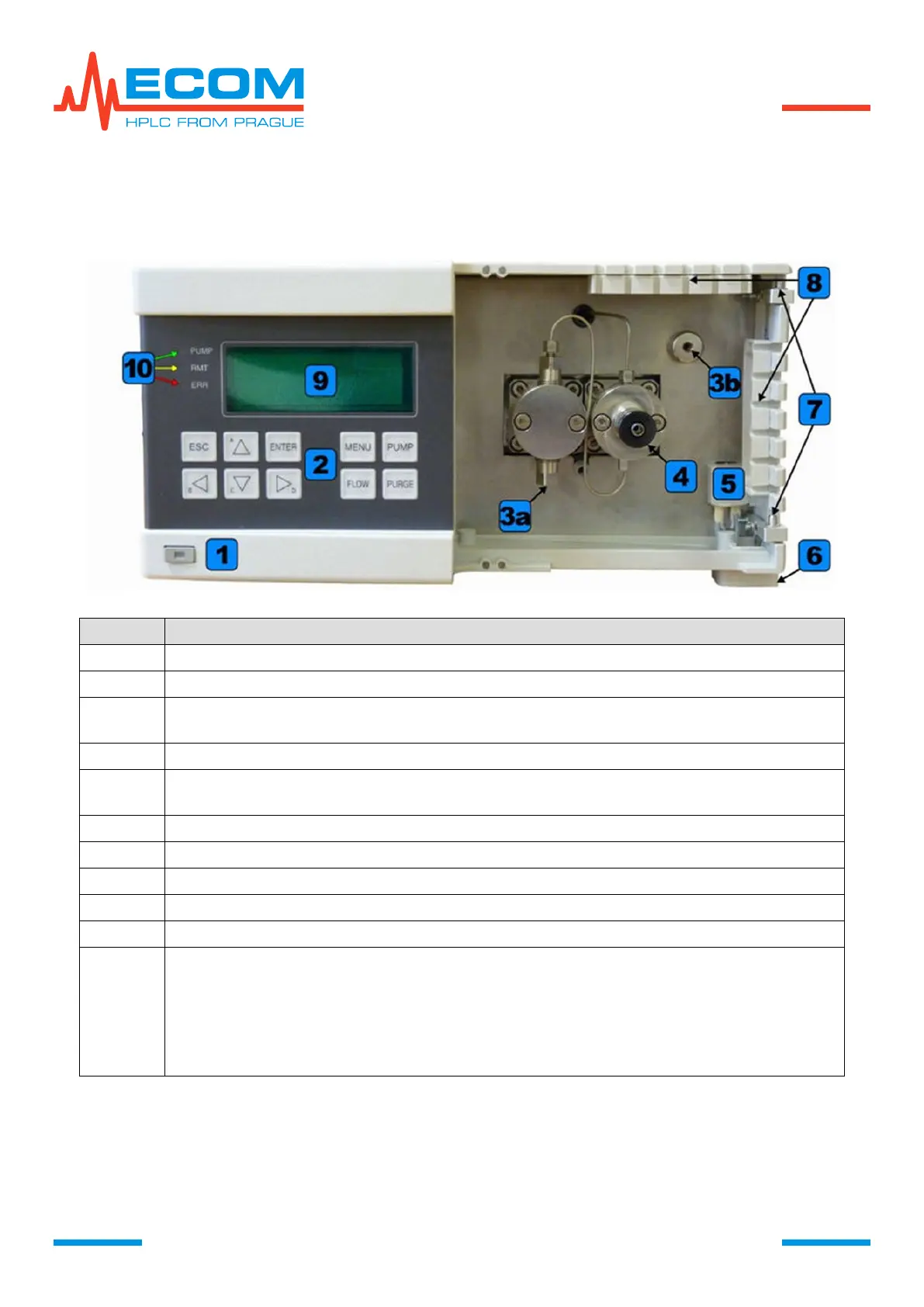
Connection for input tubing (pump inlet) working block with pumping and washing
head (behind the pumping head).
3b
Connection for output capillary (pump outlet).
4
Washing/degassing (bypass) valve compensating block with pumping and washing
head.
5
Leakage sensor.
6
Drain channel with cone for connecting waste system.
7
Door hinges.
8
Slots for tubing and capillaries.
9
Display.
10
Status LED:
PUMP (green) for indication of pump motor status (PUMP and PURGE).
RMT (yellow) for indication of unit remote control status. If it is on, the unit
communicates through ETHERNET or RS232 interface.
ERR (red) for indication of unit error status. If it is on, there is an error indicated, if it
blinks, there is a fatal error indicated and unit status has changed.

Table of Contents