49
2
Hardware Installation
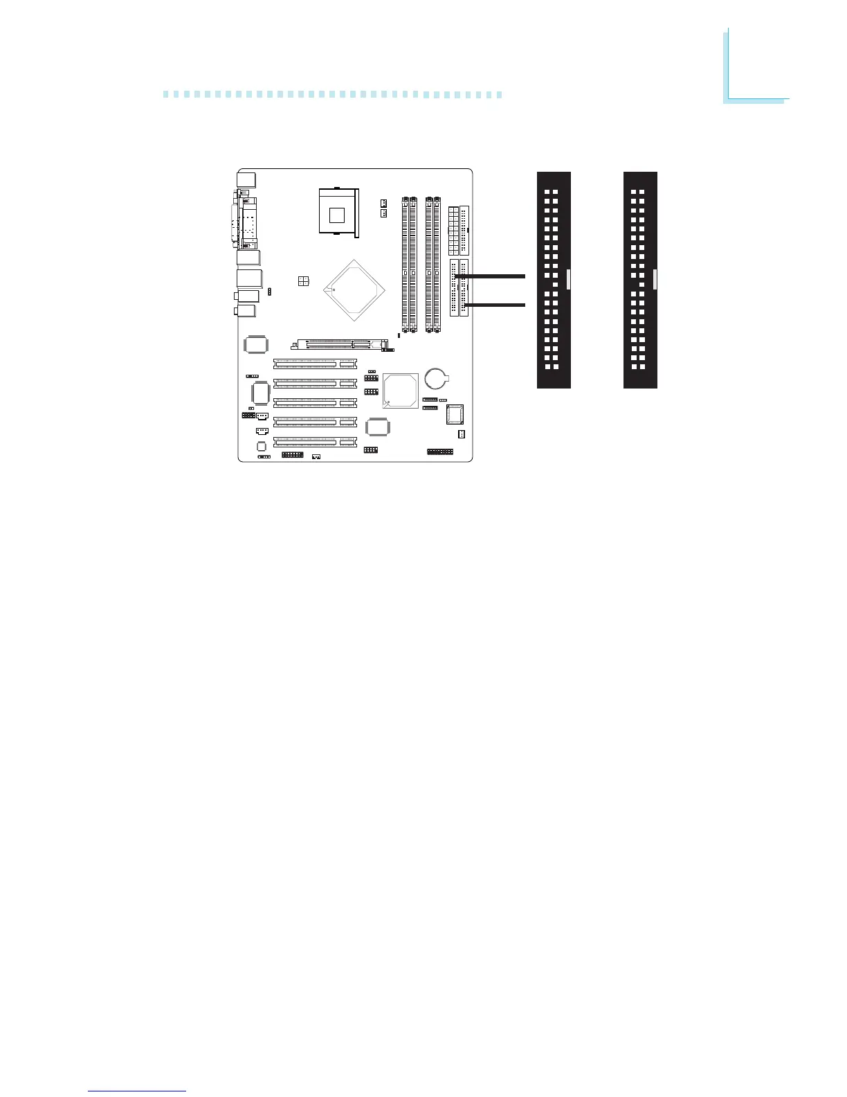
2.6.5 IDE Disk Drive Connector
The system board is equipped with two shrouded PCI IDE head-
ers that will interface four Enhanced IDE (Integrated Drive Elec-
tronics) disk drives. To prevent improper IDE cable installation,
each shrouded PCI IDE header has a keying mechanism. The 40-
pin connector on the IDE cable can be placed into the header
only if pin 1 of the connector is aligned with pin 1 of the header.
Each IDE connector supports 2 devices, a Master and a Slave.
Use an IDE ribbon cable to connect the drives to the system
board. An IDE ribbon cable have 3 connectors on them, one that
plugs into an IDE connector on the system board and the other
2 connects to IDE devices. The connector at the end of the cable
is for the Master drive and the connector in the middle of the
cable is for the Slave drive.
Connecting the IDE Disk Drive Cable
Install one end of the IDE cable into the IDE 1 header (J23) on
the system board and the other connectors to the IDE devices.
If you are adding a third or fourth IDE device, use another IDE
cable and install one end of the cable into the IDE 2 header
(J21) on the system board and the other connectors to the IDE
devices.
40
39
21
IDE 2
40
39
21
IDE 1
IDE 2
IDE 1