Cadence II Fetal Monitor Service Manual
- 39 -
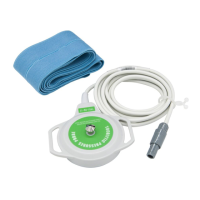
Figure 3-13 setting the print board
connecting the wires fixup the board
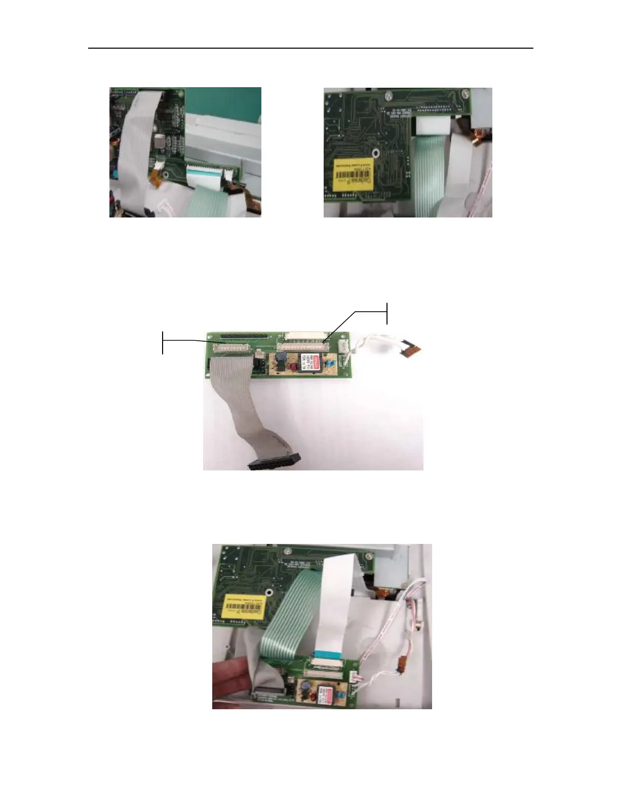
3.6 installing the interface board
Figure 3-15 the interface board
NOTE: connecting the 20pins and 30pins sockets with correspondings in the
figure3-5 after setting the inteface board.
Figure 3-16 connecting the wires
The 20pins socket
The 30 pins socket
 Loading...