Cadence II Fetal Monitor Service Manual
- 13 -
Definitions for power supply output jack pins:
PIN No. Function Description
PIN1(yellow) D.C. supply output pin: VDD (+12V)
PIN2 (red) D.C. supply output pin: Vcc (+5V)
PIN3 Null
PIN4、PIN5 (black)
Earth: 0V
PIN6 (blue) D.C. supply output pin: VEE (-12V)
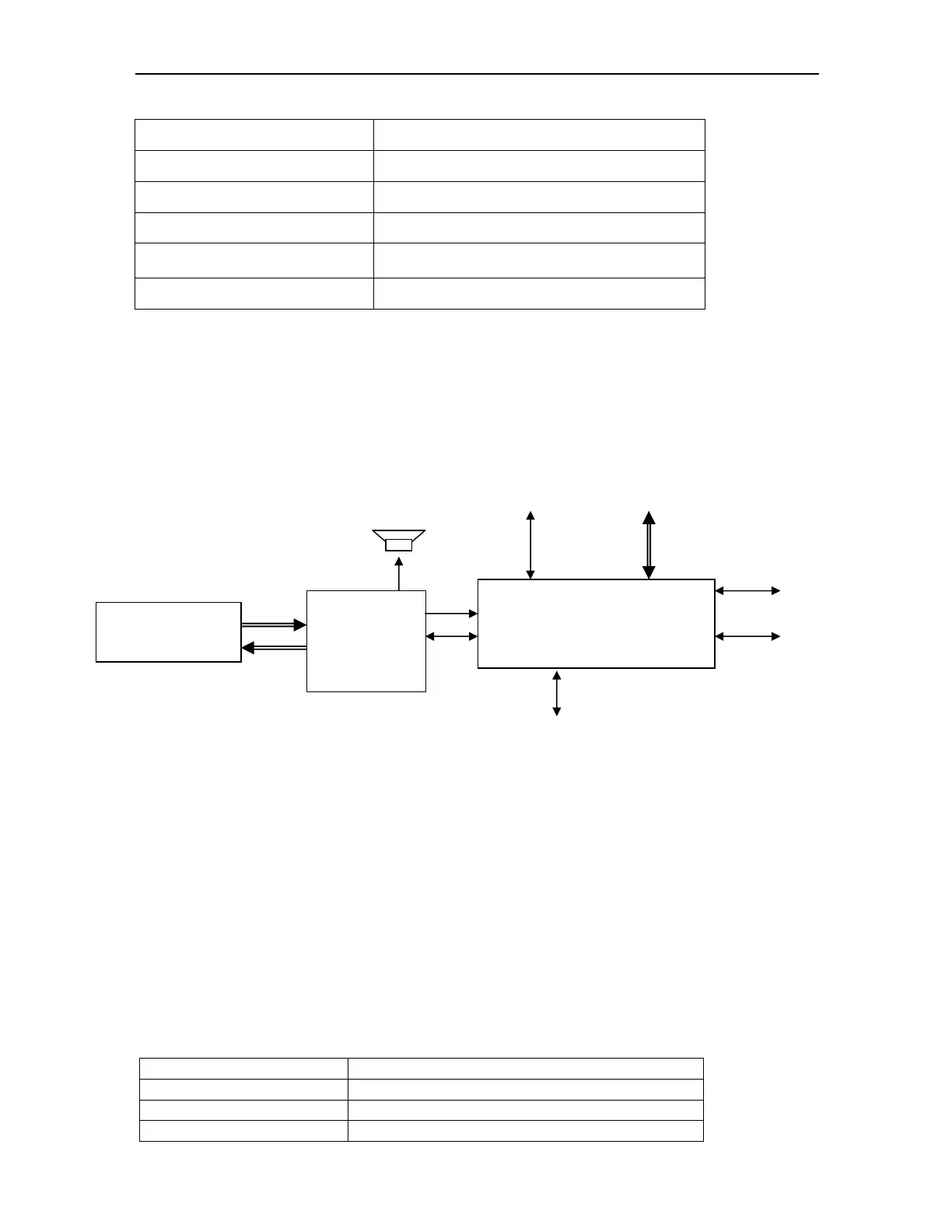
1.3.2 Mainboard
Mainboard includes key input control, LCD display, process print, audio alarm and led
indicate light alarm, data memorize and recall , time and date management,
communication with the internal modules ,ect.
Interface function is as follows:
Define interface:
Parallel Interface 1: send out command (ESC protocol) to thermal printer for printing via
print interface.
Serial Interface 2: send out command to LCD display module for data display, and
receive keyboard command.
Serial Interface 3: communicate with central station. Transmit data and receive
command from central station.
Definitions for each jack pin on the mainboard are as follows:
Definitions for power supply jack J2 pins:
PIN No. Function Description
PIN1 VCC
PIN2 Earth: 0V
PIN3 Earth: 0V
ATMEGA128 Main Control
Process data keyboard command,
display/ print results, system
management
DSP
TMS320F206
Audio Drive
FHR Ultrasound
TOCO Pressure
RS-232C/RS-485
POWER control unit
Parallel interface
Print control
Keyboard
LCD display

 Loading...