Chapter 5
| Switch Management
Understanding the Switch Status LEDs
– 34 –
Understanding the Switch Status LEDs
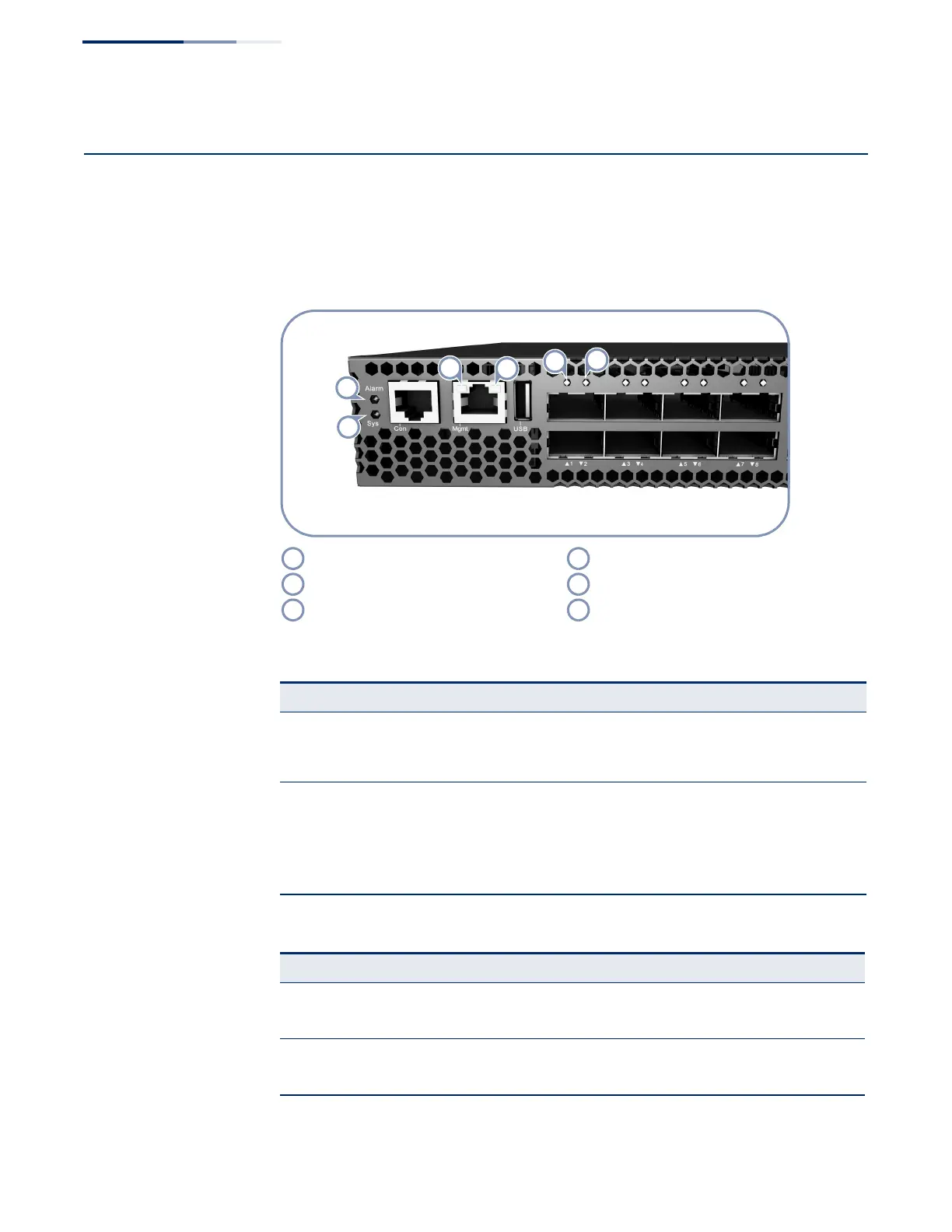
The switch includes LED indicators on the front panel that display system and port
status. Understanding the LED states will help you monitor switch operation and
alert you to any problems.
Figure 17: System and Port Status LEDs
Management Port Link LED Lower QSFP+ Port LED
Management Port Activity LED System LED
Upper QSFP+ Port LED Alarm LED
Table 5: System Status LEDs
LED Condition Status
Alarm On Green The system is operating normally.
Flashing Red The system detected a fault; either a PSU, fan, or thermal
condition.
Sys On Green Power is on and the system is operating normally.
Flashing Green The system is booting-up.
On Amber The system has been reset.
Off There is no power being received.
Table 6: Management Port Status LEDs
LED Condition Status
Left LED (Link) On Green Port has a valid link.
Off The link is down.
Right LED (Activity) Flashing Green Activity on the port.
Off The link is down.

 Loading...