– 23 –
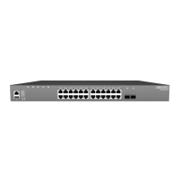
3 Switch Chassis
The switch is designed to be installed in a standard 19-inch equipment rack.
Before continuing with switch installation, first review the general guidelines and
switch cooling requirements in this chapter.
This chapter includes these sections:
◆ “General Installation Guidelines” on page 23
◆ “How to Install the Switch in a Rack” on page 24
◆ “Switch Cooling Requirements” on page 26
General Installation Guidelines
Be sure to follow the guidelines below when choosing a location.
◆ The installation location should:
■
be able to maintain its temperature within -40 to 70 °C (-40 to 158 °F) and
its humidity within 5% to 95%, non-condensing.
■
provide adequate space (approximately five centimeters or two inches) on
all sides for proper air flow.
■
be accessible for installing, cabling and maintaining the device.
■
allow the status LEDs to be clearly visible.
◆ Make sure twisted-pair cable is always routed away from power lines,
fluorescent lighting fixtures and other sources of electrical interference, such as
radios and transmitters.
◆ Make sure that the unit is connected to a separate grounded power outlet and
is powered from an independent circuit breaker. As with any equipment, using
a filter or surge suppressor is recommended. Verify that the external power
requirements for the switch can be met as listed under “Power Supply
Modules” on page 29.