Chapter 3
| Switch Chassis
Switch Cooling Requirements
– 28 –
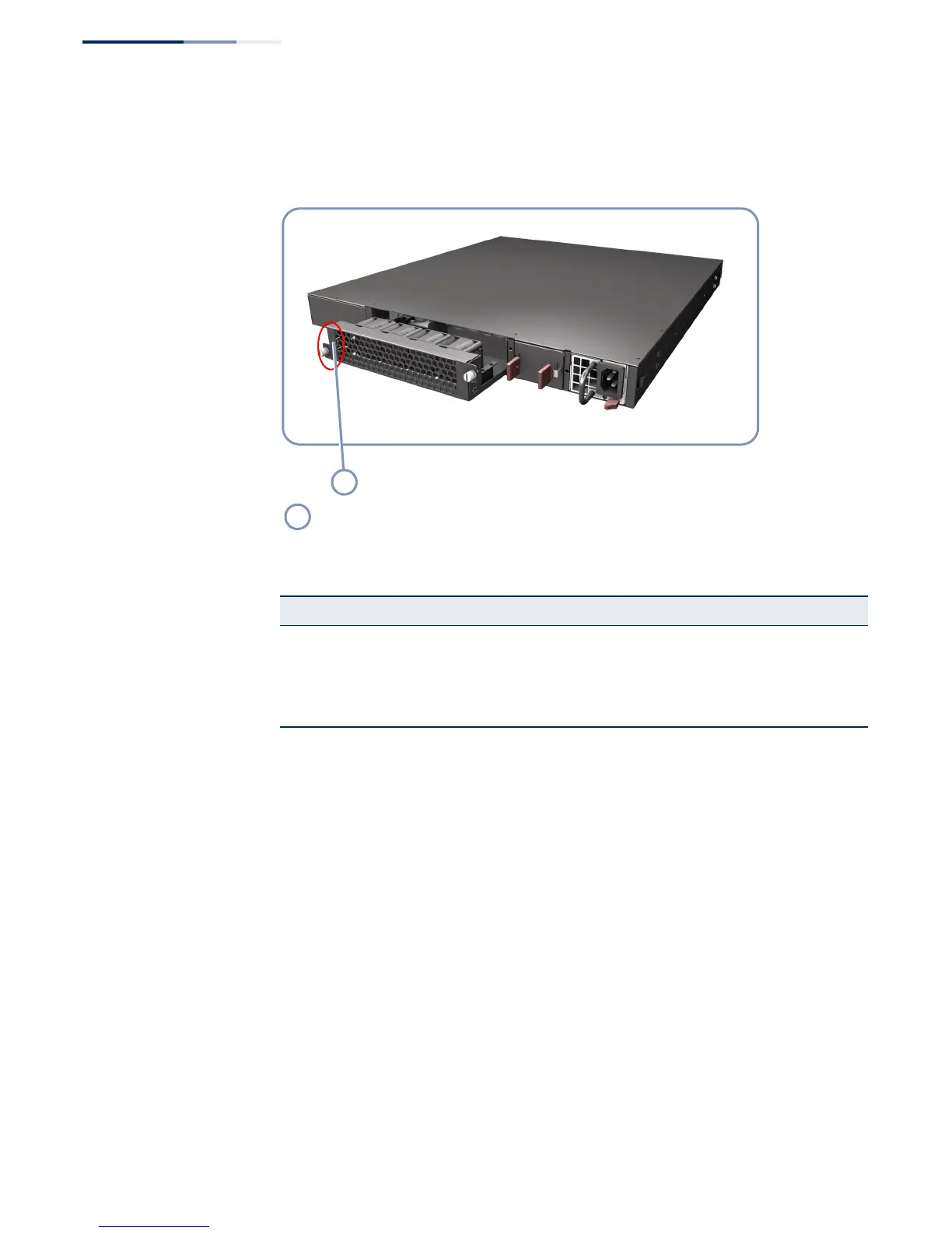
The following figure shows the fan tray removed from the switch.
Figure 15: Fan Tray
How to Replace a Fan
Tray
The switch system is shipped with a fan tray module installed. If a fan failure is
detected (see “Understanding the System Status LEDs” on page 48), the module
should be replaced immediately.
Follow this procedure to replace a fan tray:
1. Loosen the two retaining screws on the front panel of the fan tray.
2. Pull firmly on the screws until the fan tray is free.
3. Slide the fan tray out of the switch.
4. Insert the replacement fan tray into the slot and slide it slowly into the chassis.
5. Push firmly until the fan tray clicks into place. The fans should immediately start
to operate.
6. Tighten the retaining screws to secure the fan tray in the chassis.
Label indicates airflow direction
Table 2: Fan Tray Specifications
Item Description
Power Consumption 12 VDC @ 2.8 A, 37 Watts maximum
Airflow 76.4 CFM minimum
90.4 CFM maximum
Dimensions W x D x H: 207 x 94.25 x 40.4 mm (8.15 x 3.71 x 1.59 inches)
 Loading...