CET Electric Technology
18
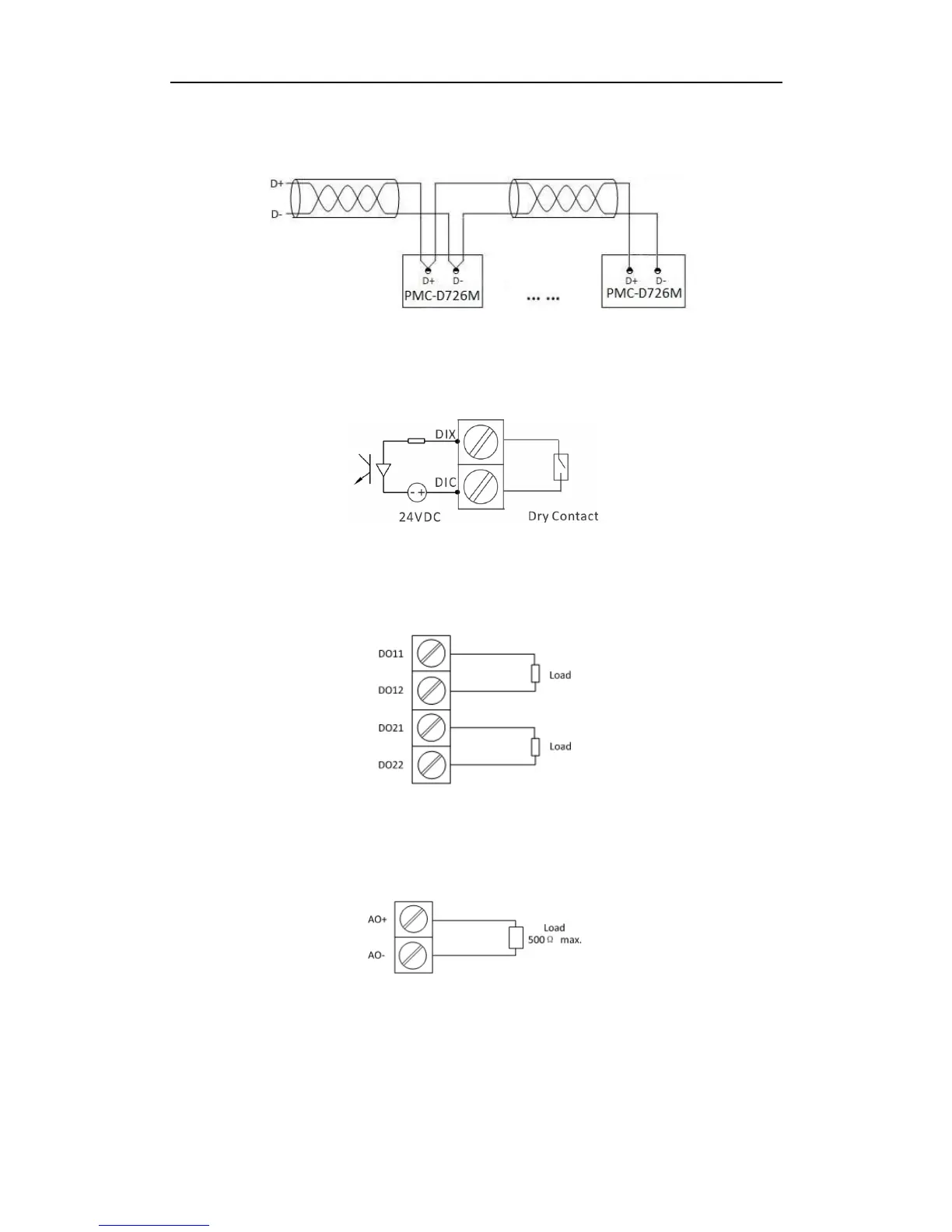
converter with optically isolated output and surge protection should be used. The following figure
illustrates the RS-485 connections on the PMC-D726M.
Figure 2-18 Communications Connections
2.6 Digital Input Wiring
The following figure illustrates the Digital Input connections on the PMC-D726M:
Figure 2-19 DI Connections
2.7 Digital Output Wiring
The following figure illustrates the Digital Output connections on the PMC-D726M:
Figure 2-20 DO Connections
2.8 Analog Output Wiring
The following figure illustrates the Analog Output connections on the PMC-D726M:
Figure 2-21 AO Connections
2.9 Pulse Output Wiring
The following figure illustrates the Pulse Output connections on the PMC-D726M: