CET Electric Technology
32
correspond to the per phase PF. For example, if the PF is 0.5 Lag and the Voltage phase angles are 0.0°,
240.0° and 120.0°, the Current phase angles should have the values of -60.0°, 180.0° and 60.0°.
4.3.2 Power Quality Parameters
The PMC-D726M provides the following PQ parameters:
4.3.2.1 Harmonics
The PMC-D726M provides harmonic analysis for THD, TOHD, TEHD and individual harmonics up to the
31
st
order. All harmonic parameters are available through communications. In addition, the PMC-D726M
also provides TDD, K-factor and Crest-factor measurements for Current.
4.3.2.2 TDD
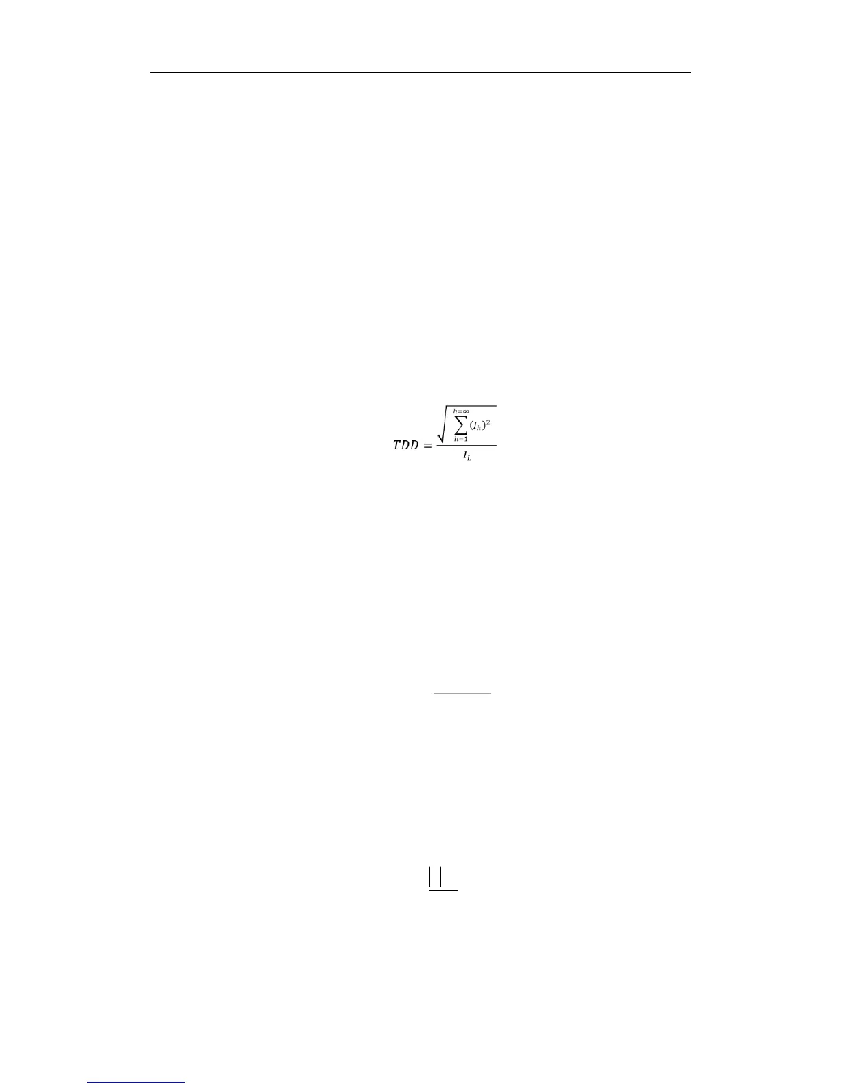
Total Demand Distortion (TDD) is defined as the ratio of the root mean square (rms) of the harmonic
current to the root mean square value of the rated or maximum demand fundamental current.
TDD of the current I is calculated by the formula below:
where
I
L
= maximum demand of fundamental current
h = harmonic order (1, 2, 3, 4, etc.)
I
h
= rms load current at the harmonic order h
4.3.2.3 K-Factor
K-Factor is defined as the weighted sum of the harmonic load current according to their effects on
transformer heating, as derived from ANSI/IEEE C57.110. A K-Factor of 1.0 indicates a linear load (no
harmonics). The higher the K-Factor, the greater the harmonic heating effect.