#
Available in Firmware Version V1.00.04 (LED)/V1.01.04 (LCD) or later
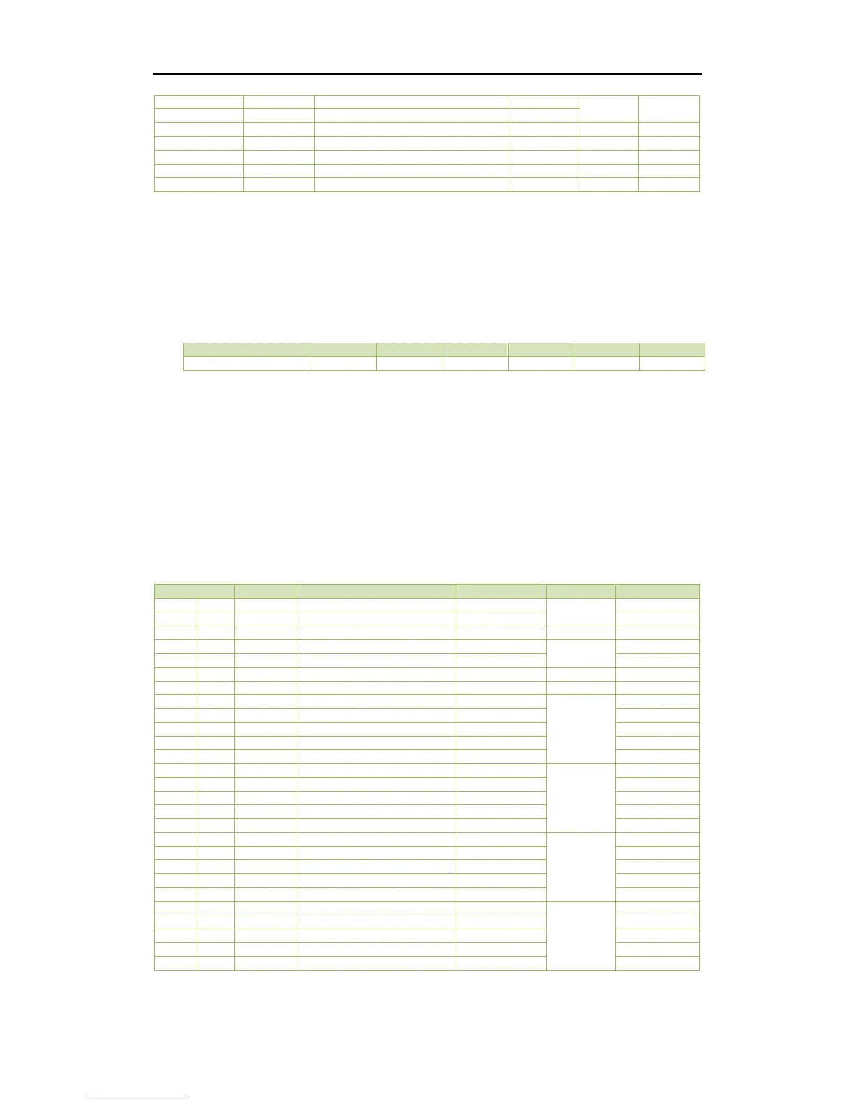
Table 5-1 Basic Measurements
Notes:
1) When the Wiring Mode is Delta, the per phase line-to-neutral voltages, kWs, kvars, kVAs and PFs have no
meaning, and their registers are reserved.
2) “×100” indicates the value returned in the register is 100 times the actual engineering value with the unit V
(voltage). For example, if the register contains a value 22003, the actual voltage is 22003/100=220.03V.
3) For the Setpoint Status register, the bit values indicate the various Setpoint states with “1” meaning Active
and “0” meaning Inactive. The following table illustrates the details of the Alarm Status register.
Table 5-2 Alarm Status Register
4) For the DO Status register, the bit values of B0 and B1 represent the states of DO1 and DO2, respectively, with
“1” meaning Active (Closed) and “0” meaning Inactive (Open).
5) For the DI Status register, the bit values of B0 and B1 represent the states of DI1 and DI2, respectively, with
“1” meaning Active (Closed) and “0” meaning Inactive (Open).
6) The range of the SOE Pointer is between 0 and 0xFFFFFFFF. The SOE Pointer is incremented by one for every
event generated. If a CLR SOE is performed from the front panel or via communications, the SOE Pointer will
be reset to zero and then immediately incremented by one with a new ”Setup Changes via Front Panel” or
“Setup Changes via Communications” event. Therefore, any 3
rd
party software should assume that a CLR SOE
action has been performed if it sees the SOE Pointer rolling over to one or to a value that is smaller than its
own pointer. In this case, the new SOE Pointer also indicates the number of events in the SOE Log if it is less
than 16. Otherwise, there will always be 16 events in the SOE Log.
5.2 Energy Measurements