14Service Guide: EFI Fiery Central integrated server
Replacing parts
Fiery Central integrated server overview diagrams
The following figures provide an overview of FC integrated server components.
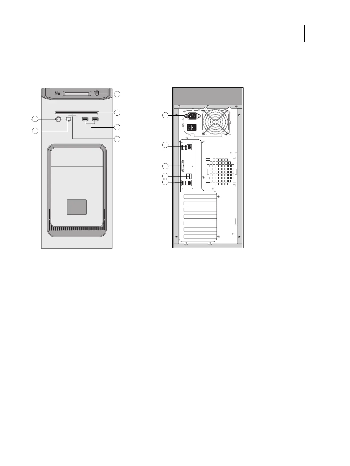
Figure 2: Front panel and connector panel
Front panel Connector panel
1 Power button 7 Power connector
2 Reset button 8 USB ports (x2) and network port (RJ-45)
3 Control panel 9 DVI port (VGA signal)
4 DVD drive 10 USB ports (x2)
5 USB ports 11 USB ports (x2) and scan port (RJ-45)
6Eject button
Note: Use the reset button only if the system is unresponsive to keyboard or mouse actions.