24Service Guide: EFI Fiery Central integrated server
Replacing parts
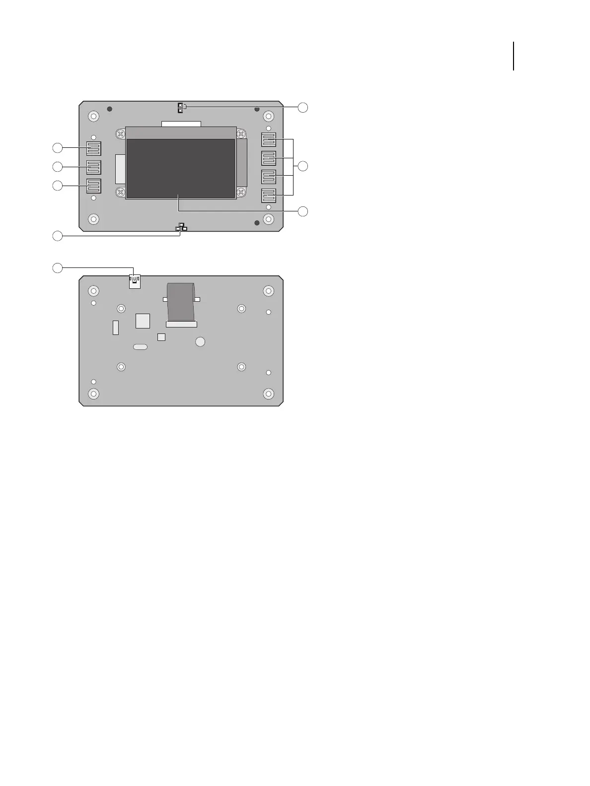
Figure 9: Diagram of the user interface board (front and back)
To remove the user interface board
1 Shut down and open the FC integrated server (see page 18).
To access the UIB, you must remove the left, right, front, and top panels.
Note: Be sure to detach the UIB cable from its connector on the motherboard, and then carefully route the cable
out of the hole in the top of the chassis as you remove the top panel.
2 Turn the top panel over to expose its underside and place it on a padded surface.
3 Detach the UIB cable from the connector on the back of the UIB.
Detach the UIB cable by grasping the cable connector. Avoid pulling on the cable.
Front view Back view
1 Up button pad 8 UIB cable connector to J27
2 Menu button pad
3 Down button pad
4 Jewel lights
5 Activity lights (LEDs)
6 Line selection button pads
7 Display window