ELAN HC6/HC12 INSTALLATION MANUAL
© ELAN 2010 | All rights reserved.
Page 39
PPWM Precision Panel (Continued)
IR Link
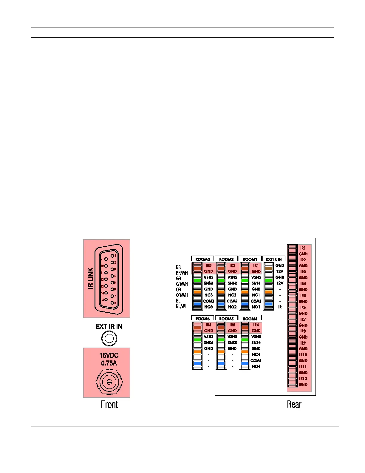
The IR Link connects to the IR Link of the System Controller using a DB15 cable. It
provides connections from the HC6 or HC12 to IR controlled devices. The first six IR
inputs from the IR Link and the six 3.5mm IR inputs are parallel and send IR to the first six
110 punch-downs on the rear of the PPWM. They also send IR to the “Room” punch-
down IR connections. IR “1” sends IR to Room 1, IR “2” sends IR to Room 2, etc. The six
additional IR connections from the IR Link are made available using 110 punch-downs # 7
through # 12 on the reverse of the PPWM. See Figure 5-2 below.
Use Cat5 to extend the IR signals to emitters connected to PPRM panels located in zones.
When using the IR Link connection for any of the first six IR outputs, DO NOT connect
the 3.5mm connection for that output. This could cause unintended duplication of IR
commands.
When using the IR Link connection, the 16 VDC power supply must be connected. The
IR Link signal from the System Controller is 3 VDC. The power supply is required to
increase the strength to 12 VDC to operate emitters.
Figure 5-2: IR Link Connection
 Loading...